smd power inductors measurements

oliver

New Member
Thread Starter
Joined
May 24, 2017
Messages
108
Location
Italy
Hi John,
i have made a set of measurements for some smd shielded power inductors, in the range 22uH-5.6mH.
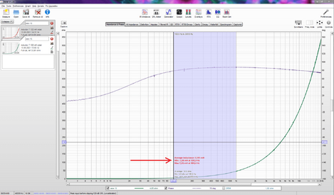
In the description of each measure there is the inductance value and the DCR as stated by the manufacturer. In the notes, the first line between the brackets is the measure made at 1KHz with a software with a LRC function, the second line is the measure of the DCR with a milliohms meter.
As you can see, the values measured by the different methods are all very similar.
Thank you for your great work with REW.

Best Regards,
Oliver.
it seems I cannot attach the mdat file..
 

oliver

New Member
Thread Starter
Joined
May 24, 2017
Messages
108
Location
Italy
Mdat part 1
 

Attachments

  • SMD shielded power inductors 22uH-5.6mH(part 1).mdat.zip
    13 MB · Views: 26

oliver

New Member
Thread Starter
Joined
May 24, 2017
Messages
108
Location
Italy
Mdat part 2
 

Attachments

  • SMD shielded power inductors 22uH-5.6mH(part 2).mdat.zip
    13 MB · Views: 17

John Mulcahy

REW Author
Joined
Apr 3, 2017
Messages
7,212
Thanks very much for posting those, they showed up a bug in the Component Model, it was giving wrong values for the equivalent circuit series R. I have fixed it for the next build.
 

sm52

Member
Joined
Mar 14, 2019
Messages
863
John hi.
I have a measurement of two inductors. Each file has two measurements in a row. The device, an immittance meter, having an open circuit and short circuit calibration, showed the inductance values for these inductors, which are in the file name. Looking at the component model, Lsum doesn't fit (a little). If you look at the window at the bottom left of the graph, then the readings of the device correspond to the value of the inductance in the series equivalent circuit at a frequency of 1.5 kHz (about that). If you needed to measure the inductor with REW and then indicate its value on the circuit, which value should be used?
 

Attachments

  • inductor 3.387 mH.mdat
    7.5 MB · Views: 15
  • inductor 7.122 mH.mdat
    7.5 MB · Views: 17

John Mulcahy

REW Author
Joined
Apr 3, 2017
Messages
7,212
I have a measurement of two inductors. Each file has two measurements in a row. The device, an immittance meter, having an open circuit and short circuit calibration, showed the inductance values for these inductors, which are in the file name. Looking at the component model, Lsum doesn't fit (a little). If you look at the window at the bottom left of the graph, then the readings of the device correspond to the value of the inductance in the series equivalent circuit at a frequency of 1.5 kHz (about that). If you needed to measure the inductor with REW and then indicate its value on the circuit, which value should be used?
I'd be inclined to use the inductance where the phase levels off and before it starts dropping again, which is at around 1 kHz for those inductors. For circuit simulation/modelling I'd use REW's equivalent circuit though.
 

oliver

New Member
Thread Starter
Joined
May 24, 2017
Messages
108
Location
Italy
Part 2 seems to have the same measurements as part 1, the last is 220 uH. Could you post the additional measurements for the higher value inductors?
Sorry John,
Here it is.
 

Attachments

  • SMD shielded power inductors 22uH-5.6mH(part 2).mdat.zip
    9.6 MB · Views: 18

sm52

Member
Joined
Mar 14, 2019
Messages
863
John,
I want to return to the question of the measurement result. I measured the impedance of the inductor. Let's say I don't have a separate inductance meter. Where can I get the inductance value of the measured inductor? If follow the advice in post 7, then it is difficult to determine the point where the phase begins to fall. If move the cursor back and forth near this place, the inductance value jumps back and forth. On the second graph in my post 5 near 1 kHz shows 7.15-7.21-7.16 mH. The component model shows 6.96 mH. And if we consider that such an inductor is used as a first-order filter, then its operating frequency is 100 Hz. At 1 kHz, it almost does not affect at the frequency response graph. Near 100 Hz, its inductance is 7.19-7.20 mH. To use an inductor in a circuit, need to know its exact value. And with three decimal places. Because there is a difference, 7.121mH or 7.129mH. If you look at the latest oliver's .mdat, the last measurement, then 5.6 mH can only be seen at 20 kHz. And the component model is 12.4 mH. Is there any way to calculate the value of the inductance that is measured? Let's say as the average in a user-specified frequency range.
 
Last edited:

John Mulcahy

REW Author
Joined
Apr 3, 2017
Messages
7,212
The effects of leakage and series resistance mean the inductor does not have a single value that will reflect its behaviour at different frequencies. The component model shows what the inductor actually behaves like. The cursor overlay shows the values for a simpler series or parallel RL pair valid at the cursor frequency.
 

sm52

Member
Joined
Mar 14, 2019
Messages
863
This can be understood as a general description of the behavior of the inductor. But if you use REW to measure inductance and use the measured value in a circuit or crossover simulator, an accurate value is required. Agree that the inductance of an inductor cannot vary from 900 Hz to 1100 Hz in this way - 7.15-7.21-7.16 mH. It's more of a computational overhead. Is it possible to calculate the average value of inductance and resistance on a selected or user-specified frequency range? For example, as in the picture.
 

Attachments

  • Inductor 7.122mH.PNG
    Inductor 7.122mH.PNG
    113 KB · Views: 22

John Mulcahy

REW Author
Joined
Apr 3, 2017
Messages
7,212
I don't see how that would make sense. At one end of that range you have an equivalent series R of 950 mohm, at the other 2.3 ohm. If precision is important replace the inductor in your schematic with the component model, since that reflects how the component behaves, and generate your simulator responses from that. That is what the component model is for. It is contradictory to say that you need an inductance figure accurate to 3 decimal places but then to ignore the leakage and winding resistance effects.
 

sm52

Member
Joined
Mar 14, 2019
Messages
863
Okay. I will be using the Lsum inductance from the component model. Does it make sense to add a third decimal place in the component model?
 

John Mulcahy

REW Author
Joined
Apr 3, 2017
Messages
7,212
I think you misunderstand me. I do not mean use Lsum, I mean use the two resistors and two inductors of the component model in place of the single idealised inductor of your crossover circuit.
 

sm52

Member
Joined
Mar 14, 2019
Messages
863
This is unexpected. It seems to me that no one tried to do it. I'll try. But the third decimal place in the component model would still be desirable.
 

trobbins

Member
VIP Supporter
Joined
Nov 26, 2017
Messages
121
Location
Australia
sm52, perhaps you need to assess what impact the tolerance of one part (the inductor) has in your application first. Perhaps use your crossover simulator to identify the impact of a 1% change in part inductance. After that you perhaps should assess all the other crossover part tolerances, and assess the final affect of the combination of tolerances (eg. does this relate to 1dB or 0.1dB or 0.001dB difference in response at a particular frequency).

Also may be worthwhile appreciating how the inductance value changes with applied signal voltage. Your measurement setup applies a certain voltage level to the part. What voltage level is applied to the part in its application? Can you make your impedance measurement at different voltage levels?
 

sm52

Member
Joined
Mar 14, 2019
Messages
863
trobbins,
thank you for your advice. Why I was talking about the third decimal place - I tweaked the existing inductor for the best sound along with the other ways of speaker. Not with a crossover simulator, but by adding or subtracting turns of wire. It turned out that there is only one variant, when all the ways are playing well. + half a turns, minus half a turns - and the sound picture ceases to be interesting. This difference is the third decimal place in the inductance value. After getting a good result in one copy, then you need to repeat the same for another copy. The crossover simulator gives a too rough picture, it is needed in order not to make gross mistakes.
 

jschwender

Member
Joined
Mar 16, 2021
Messages
140
Location
GERMANY
More  
Front Speakers
Nubert digital pro
Other Speakers or Equipment
Philips dss940
If the inductor has a magnetic core other than air, it will always have a inductance that depends on frequency, temperature, current…. Even with air core, if you wind wire on a plastic former like a modern PBT GF, which has a linear thermal expansion coefficient of 1E-5/K and you increase T by 100°C it will end up in length and diameter change of 1E-3, here you are at third decimal. Even worse, the magnetic field ends up in physical forces to the windings, and as the former has a finite elasticity module it will deform, which also changes your inductance. From my experience with manufacturing coils, i would seriously state that measuring such a coil to the third decimal is only possible for a fixed current, a fixed temperaure and a fixed frequency. And accuracy is something different than a specific number of decimals as result calculation. You will certainly not archieve this measurement precision with tools like REW, go and try to calculate the theory of error for the principle that REW uses, and you will see why. The only way to do such a precision measurement is to measure the resonance frequency in series with a given precision capacity at a given current and frequency. Also any RLC meter does not do that, it usually cannot run at selectable frequency or current. You need to buy something like a Wayne Kerr WK3255, it has a base accuracy of 0.1%.
 

sm52

Member
Joined
Mar 14, 2019
Messages
863
The device I have measures with three decimal places. Yes, on two fixed frequencies. Whether I can trust him is not so important. If 5 measurements in a row he shows the same thing - I will trust him. If REW shows 5 measurements in a row the same thing - I will trust him. That is, all elements will be measured with the same error. This is a criterion for me to work with such a device.
 

trobbins

Member
VIP Supporter
Joined
Nov 26, 2017
Messages
121
Location
Australia
sm52, you may be digging yourself a hole with the 3 decimal places. Seeing parameter values with that many decimal places being attested to is a red-flag for some of us. It is likely that changing the applied signal voltage could change the inductance of a non-air cored inductor by >1% - so if the application has music or other signal variation, then your crossover may have a moving crossover frequency. It's just about better appreciating the parts you use - as it likely won't change the nominal value of parts you select for a crossover.
 

sm52

Member
Joined
Mar 14, 2019
Messages
863
I agree that inductance can vary slightly with temperature. Even holding an inductor in your hands - and inductance will become a little larger. But my thoughts and yours are tested in practice. When I set up something, I always listen to draw conclusions about the action taken. Sometimes I invite friends for confirmation. Then you can go into the question of subjectivity. Thank you for your thoughts, we have already allowed ourselves a lot within the framework of this thread.
 
Top Bottom