


-
AUDIO VIDEO PROCESSING, SETUP & ENVIRONMENTOfficial REW (Room EQ Wizard) Support Forum Audiolense User Forum Calibration Equipment Auto-EQ Platforms / Immersive Audio Codecs Video Display Technologies / Calibration AV System Setup and Support Listening Room / Home Theater Build Projects Room Acoustics and Treatments AV Showcase Movies / Music / TV / Streaming
-
AUDIO VIDEO DISCUSSION / EQUIPMENTHome Theater / Audio and Video - Misc Topics Essence For Hi Res Audio AV Equipment Advice and Pricing Awesome Deals and Budget AV Equipment AV Receivers / Processors / Amps UHD / Blu-ray / CD Players / Streaming Devices Two Channel Hi-Fi Equipment DIY Audio Projects Computer Systems - HTPC / Gaming HD and UHD Flat Screen Displays Projectors and Projection Screens AV Accessories Buy - Sell - Trade
Navigation
Install the app
How to install the app on iOS
Follow along with the video below to see how to install our site as a web app on your home screen.
Note: This feature may not be available in some browsers.
More options
You are using an out of date browser. It may not display this or other websites correctly.
You should upgrade or use an alternative browser.
You should upgrade or use an alternative browser.
Speaker Impedance measurement ,circuit and sound card output
- Thread starter icbcodc
- Start date

No amplifier, Yamaha-Steinberg UR22 mk2 soundcard with last drivers.Bernard
Was there only external sound card or sound card + amplifier in your T / S measurements?
Ordinary Thomann cables except 100 ohms Rsense resistor, VISHAY 0,01% VSRJ RS92N Metal Foil Resistance Resistor 100 Ohms (99.945 ohms measured) and ref resistor calibration Rni12 TLHP non inductive high precision resistor 33 ohm 5% (32.81 ohms measured).
* Measurement data measured by REW V5.20 Beta 55
* Source: ASIO Yamaha Steinberg USB ASIO, UR22mkII Input 2
* Format: 512k Log Swept Sine, 1 sweep at -10,1 dBFS, at 48000 Hz
* Dated: 24 juin 2020 11:47:38
* Sense Resistor: 99.9
* Lead resistance: 0.322
* Input resistance: 20000.000
* Calibration factor: 0.9993
John Mulcahy
REW Author
- Joined
- Apr 3, 2017
- Posts
- 9,379
Impedance measurement noise levels are affected by the output impedance of the source. A soundcard with a capacitively-coupled output (most commonly the case) and a high output impedance will give poor and noisy results at the lowest frequencies. Cards with high output power capability, low output impedance and DC-coupled outputs give the most accurate results (ADI-2 Pro using its high power headphone output as an expensive but very high-performing example). A power amplifier is a way to achieve greatly reduced output impedance, but requires additional circuitry to protect the soundcard from high voltages which could destroy it.
The dual added mass method, per the analysis in Claus and Jeff's paper, is capable of about +/-1% accuracy in Mms determination, based on the variation in results obtained by 4 individuals (experienced testers, I believe) conducting a series of tests. Even for those individuals 3 of 21 tests were rejected due to unreliable results. The driver used for the tests, L16RNX, is noted as perhaps presenting a best case scenario as its suspension compliance changes very little with movement of the cone. Large low frequency drivers can exhibit quite large compliance variability following displacement of the cone, when attaching or removing weights, for example, so obtaining repeatable results with such a driver can be very challenging and not necessarily a good use of time.
The dual added mass method, per the analysis in Claus and Jeff's paper, is capable of about +/-1% accuracy in Mms determination, based on the variation in results obtained by 4 individuals (experienced testers, I believe) conducting a series of tests. Even for those individuals 3 of 21 tests were rejected due to unreliable results. The driver used for the tests, L16RNX, is noted as perhaps presenting a best case scenario as its suspension compliance changes very little with movement of the cone. Large low frequency drivers can exhibit quite large compliance variability following displacement of the cone, when attaching or removing weights, for example, so obtaining repeatable results with such a driver can be very challenging and not necessarily a good use of time.
In the Speakerbench manual, it is said " We recommend a stepped-sine signal measurement such that all frequency points are measured under steady-state conditions. It is our experience that a fast Chirp or Farina sweep will not result in acceptable precision. If your equipment only offers sweep options, we recommend a slow sweep to achieve reasonably high accuracy. Note: REW and DATS V3 both use a sweep. "
I have just read today the document published here: - Speaker Related Companies - Products & Services Feature Article By LIS STAFF (loudspeakerindustrysourcebook.com) and in particuliar :

There has always been some doubt about the accuracy of my measurements...
I have just read today the document published here: - Speaker Related Companies - Products & Services Feature Article By LIS STAFF (loudspeakerindustrysourcebook.com) and in particuliar :
There has always been some doubt about the accuracy of my measurements...
John Mulcahy
REW Author
- Joined
- Apr 3, 2017
- Posts
- 9,379
I couldn't identify any theoretical basis for the comment about stepped versus sweep measurements beyond the greater signal to noise ratio that is possible with sweeps. Subsequent discussions with Claus and Jeff did not identify any reason that should be the case either. REW's impedance measurements offer a noise filter option that improves sweep result S/N but even without that sweep measurements give accurate results if the sweep is not very short. REW automatically ensures impedance measurement sweeps are not too short.
Impedance measurement noise levels are affected by the output impedance of the source. A soundcard with a capacitively-coupled output (most commonly the case) and a high output impedance will give poor and noisy results at the lowest frequencies. Cards with high output power capability, low output impedance and DC-coupled outputs give the most accurate results (ADI-2 Pro using its high power headphone output as an expensive but very high-performing example). A power amplifier is a way to achieve greatly reduced output impedance, but requires additional circuitry to protect the soundcard from high voltages which could destroy it.
The dual added mass method, per the analysis in Claus and Jeff's paper, is capable of about +/-1% accuracy in Mms determination, based on the variation in results obtained by 4 individuals (experienced testers, I believe) conducting a series of tests. Even for those individuals 3 of 21 tests were rejected due to unreliable results. The driver used for the tests, L16RNX, is noted as perhaps presenting a best case scenario as its suspension compliance changes very little with movement of the cone. Large low frequency drivers can exhibit quite large compliance variability following displacement of the cone, when attaching or removing weights, for example, so obtaining repeatable results with such a driver can be very challenging and not necessarily a good use of time.
That means I need to update my circuit, so that it can be connected to my new Beringer UMC202HD soundcard which is a better one.
And I also need to find a simple way to prevent the cone from moving when I put the mass on it or take the mass off it.
icbcodc,
Before you embark on another adventure, take some time to read the article from page 124.
"In this LIS article there are graphs with 'errors' and suggestions for root causes and improvements"
https://www.calameo.com/kck-media/read/0053543533249d273ae4b?authid=AvlB4EBfh7Et
If you don't have access to it, here are the pages in pdf.
Attachments
icbcodc,
Before you embark on another adventure, take some time to read the article from page 124.
"In this LIS article there are graphs with 'errors' and suggestions for root causes and improvements"
https://www.calameo.com/kck-media/read/0053543533249d273ae4b?authid=AvlB4EBfh7Et
If you don't have access to it, here are the pages in pdf.
Thank you Bernard.
Could you help me to check your short circuit calibration? Does the value drift significantly in GD (Group Delay) tab between 10Hz TO 100Hz?
icbcodc
look at post 166. From at least 20 Hertz should be a straight line. Interference can be a working refrigerator, a network cable from a computer to a modem, a laptop power supply, the power network itself. There should be no sounds during the measurement. If there are loud sounds outside the room, it will be an obstacle. It might be worthwhile to come up with flatter weights. They will stick more easily and will not fall off. Your scales should have two decimal places. Bernard did it with 87% of Mms. I have 90%. Lay out mdat, we'll see.
look at post 166. From at least 20 Hertz should be a straight line. Interference can be a working refrigerator, a network cable from a computer to a modem, a laptop power supply, the power network itself. There should be no sounds during the measurement. If there are loud sounds outside the room, it will be an obstacle. It might be worthwhile to come up with flatter weights. They will stick more easily and will not fall off. Your scales should have two decimal places. Bernard did it with 87% of Mms. I have 90%. Lay out mdat, we'll see.
Yes, It should be a mild drift in GD tab from 20hz to 50hz which occurred in my measurements one year ago.icbcodc
look at post 166. From at least 20 Hertz should be a straight line. Interference can be a working refrigerator, a network cable from a computer to a modem, a laptop power supply, the power network itself. There should be no sounds during the measurement. If there are loud sounds outside the room, it will be an obstacle. It might be worthwhile to come up with flatter weights. They will stick more easily and will not fall off. Your scales should have two decimal places. Bernard did it with 87% of Mms. I have 90%. Lay out mdat, we'll see.
My understanding is the short circuit caliabration will not affect by environment noise,cause the subwoofer is not connected in.
If the circuit connections are O.K., the soundcard will be the source of affection in my opinion.
Calibration file attached.Could you help me to check your short circuit calibration? Does the value drift significantly in GD (Group Delay) tab between 10Hz TO 100Hz?
You know, I don't ask myself too many questions.
For the choice of the sound card, I trusted the creator of the software that suggests this card :
REW - Room EQ Wizard Room Acoustics Software
If he suggests it, it must be of good quality, not too cheap, not too expensive.
Attachments
Calibration file attached.
You know, I don't ask myself too many questions.
For the choice of the sound card, I trusted the creator of the software that suggests this card :
REW - Room EQ Wizard Room Acoustics Software
If he suggests it, it must be of good quality, not too cheap, not too expensive.
Thank you.
Actually, according to drifts in GD tab your soundcard is better than my soundcard now.

But my soundcard also done that well last year .
Now I have to migrate the circuit to the other soundcard which is only for accoustic measurement.
Here I meant measurements with masses.My understanding is the short circuit caliabration will not affect by environment noise
Here I meant measurements with masses.
I turned off the refrigrator and air conditioner, close the window and door, when making measurements.
Actually, I forgot to turn off the refrigrator in first measurement, there was a small peak on impedance curve at around 30hz.
Hello icbcodc,
Here is the analysis of Mr. Claus Futtrup from Speakerbench.
I dared to ask him if he could give you his opinion on your measurements and he immediately agreed. Isn't that great?
I sent him the attached zip file and here is what he answered during the day.
A big thank you to him.
[ Jeff Candy has the username for the AVNirvana forum. I do not, so I appreciate that you help us communicate as a middle man.
If the JL Audio woofer has a large dust cap and it is not attached directly to the voice coil, but 'hovering' - then it might be better to fix the masses near the outer edge. Each of the four masses should be in the ballpark of 40-45 gram, with four of them this should reach a total of 170 gram, which is similar to the Mms of the driver.
icbcodc needs the masses to be pushed hard onto the diaphragm, so they have a solid grip, maybe also twist them a bit so they dig into the cone surface. Without the cone moving ... I know it's not easy. If he is concerned about the visual damage, it's possibly better if they are attached around the voice coil on the back side of the speaker. Some people use pairs of neodymium magnets - they're small yet heavy.
Furthermore the transducer is very stiff (Cms = 0,20 mm/N), so if things are not moving, he should apply more voltage.
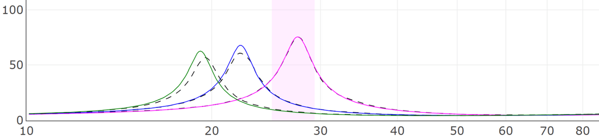
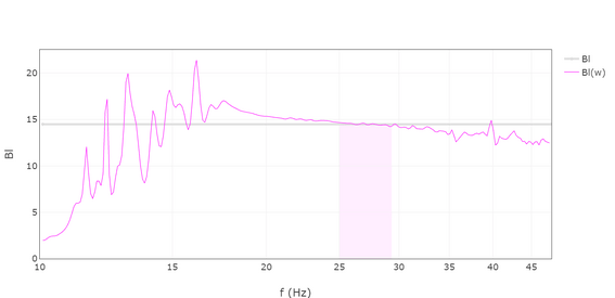
Thank you for the JSON file. I have loaded it and the Bl-curve itself doesn't look bad, except I see indications the masses are not strongly coupled to the voice coil. Between that and the model test, I think the curves from the model test most clearly show why he only gets a fair rating => there are deviations on the peaks for all three measurements (less for the one without added masses, but still a bit, maybe tolerable ... the two curves with added masses have problems).
I think he has used too small a moving mass, but to the good side, the model test shows three distinct curves (so it's not totally bad). With a larger shift in resonance (with larger masses), he should also get a more clear picture of the viscoelasticity potentially and a better fit result. ]
Now it's up to you to do the good stuff.
Cheers.
Here is the analysis of Mr. Claus Futtrup from Speakerbench.
I dared to ask him if he could give you his opinion on your measurements and he immediately agreed. Isn't that great?
I sent him the attached zip file and here is what he answered during the day.
A big thank you to him.
[ Jeff Candy has the username for the AVNirvana forum. I do not, so I appreciate that you help us communicate as a middle man.
If the JL Audio woofer has a large dust cap and it is not attached directly to the voice coil, but 'hovering' - then it might be better to fix the masses near the outer edge. Each of the four masses should be in the ballpark of 40-45 gram, with four of them this should reach a total of 170 gram, which is similar to the Mms of the driver.
icbcodc needs the masses to be pushed hard onto the diaphragm, so they have a solid grip, maybe also twist them a bit so they dig into the cone surface. Without the cone moving ... I know it's not easy. If he is concerned about the visual damage, it's possibly better if they are attached around the voice coil on the back side of the speaker. Some people use pairs of neodymium magnets - they're small yet heavy.
Furthermore the transducer is very stiff (Cms = 0,20 mm/N), so if things are not moving, he should apply more voltage.
Thank you for the JSON file. I have loaded it and the Bl-curve itself doesn't look bad, except I see indications the masses are not strongly coupled to the voice coil. Between that and the model test, I think the curves from the model test most clearly show why he only gets a fair rating => there are deviations on the peaks for all three measurements (less for the one without added masses, but still a bit, maybe tolerable ... the two curves with added masses have problems).
I think he has used too small a moving mass, but to the good side, the model test shows three distinct curves (so it's not totally bad). With a larger shift in resonance (with larger masses), he should also get a more clear picture of the viscoelasticity potentially and a better fit result. ]
Now it's up to you to do the good stuff.
Cheers.
Attachments
Hello icbcodc,
Here is the analysis of Mr. Claus Futtrup from Speakerbench.
Hi Bernard
Awesome!
I appreciate you and Mr. Claus taking the time to help me. I know Mr. Claus is professional in loudspeaker designing area and familar with structure of speakers.
If the JL Audio woofer has a large dust cap and it is not attached directly to the voice coil, but 'hovering' - then it might be better to fix the masses near the outer edge. Each of the four masses should be in the ballpark of 40-45 gram, with four of them this should reach a total of 170 gram, which is similar to the Mms of the driver.
The whole front area of this subwoofer is really a large dust cap,and it's not attached to the voice coil directly as he says.
1. I think update the four masses to around 170g with neodymium magnets is a better way, but I don't have enough time to order magnets online, I will still use butyl rubber like "Blu Tack" to achieve that.
2. I will put the masses on the outer edge of the subwoofer and push them hard to make them fixed, the front material of the cone is tough enough like plastic.
3. The real challenge is doing that without moving the cone.
4. I will still use this very old soundcard to do that,cause new connectors is not delivered yet, I cann't migrate the circuit to my new soundcard.
Hope the result will be better.


Hi జజజ
To avoid pessimism, compare the TS parameters of Speakerbench and those of REW and wait a while before measuring again!
I migrated the circuit to my soundcard UMC202HD.
I made several measurements with different mass and finally I also put the mass on the back of the cone.
The new soundcard improve the measurement result maybe, but not too much.
This Subwoofer is not easy to get good measurement.

There is only one thing left to try: more voltage.
Here attached measurements with new mass according to mms in last measurements and the new soundcard, it looks better.
Attachments
Last edited:
These are new measurements with mass which is 90% of mms.
Hi Bernard
Finally, I tried to put the mass on back of the cone.
Which one is the best ? Is there any big improvement in the results?


Last edited:


Last edited:
Thank you very much, Bernard.
I believe the problem is still there, still need to be figured out.


Popular tags
20th century fox
4k blu-ray
4k uhd
4k ultrahd
action
adventure
animated
animation
bass
blu-ray
calibration
comedy
comics
denon
dirac
dirac live
disney
dolby atmos
drama
fantasy
hdmi 2.1
home theater
horror
kaleidescape
klipsch
lionsgate
marantz
movies
onkyo
paramount
pioneer
rew
romance
sci-fi
scream factory
shout factory
sony
stormaudio
subwoofer
svs
terror
thriller
uhd
ultrahd
ultrahd 4k
universal
value electronics
warner
warner brothers
well go usa