Hello icbcodc,
Last year, in june, Mr. Jeff Candy (Speakerbench) said :
Hello, icbcodc https://www.avnirvana.com/threads/speaker-impedance-measurement-circuit-and-sound-card-output.6860/post-50908 gave me the idea to measure one of my loudspeakers with this method and to try the Speakerbench control tool : https://speakerbench.com/apps/app1 . Here is the result: "...

www.avnirvana.com
By following his instructions and John's advice to lower the weight of the masses, I got this:
Hello, icbcodc https://www.avnirvana.com/threads/speaker-impedance-measurement-circuit-and-sound-card-output.6860/post-50908 gave me the idea to measure one of my loudspeakers with this method and to try the Speakerbench control tool : https://speakerbench.com/apps/app1 . Here is the result: "...
www.avnirvana.com
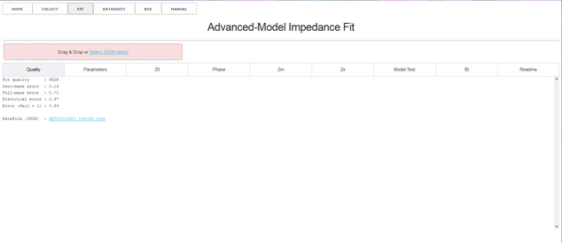
If you look at the Speakerbench quality test result, you can see that the result is "FAIR".
This did not prevent Mr. Candy from saying:
Hello, icbcodc https://www.avnirvana.com/threads/speaker-impedance-measurement-circuit-and-sound-card-output.6860/post-50908 gave me the idea to measure one of my loudspeakers with this method and to try the Speakerbench control tool : https://speakerbench.com/apps/app1 . Here is the result: "...
www.avnirvana.com
and
Hello, icbcodc https://www.avnirvana.com/threads/speaker-impedance-measurement-circuit-and-sound-card-output.6860/post-50908 gave me the idea to measure one of my loudspeakers with this method and to try the Speakerbench control tool : https://speakerbench.com/apps/app1 . Here is the result: "...
www.avnirvana.com
I have put together your Speakerbench results in the attached pdf document.
You should follow John's advice after your first simulation and consider the measurements as correct. Anyway, you can redo the T/S measurements as many times as you like and you will get different results each time.
We don't need the precision of scientists who send men to a space station! ;-)
Bernard


")