Setting t=0

sm52

Member
Thread Starter
Joined
Mar 14, 2019
Messages
863
John Mulcahy
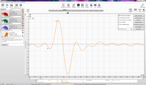
question about use timing reference. If the background noise level is low and the test impulse level is high enough, possible not use timing synchronization? In the 'Impulse' window, manually set t = 0 to the position of the impulse peak. Or to another position, near the peak, using the 'Set t = 0' tool. Will the manual setting t = 0 be the same as setting t = 0 by the program itself?
 
Last edited:

John Mulcahy

REW Author
Joined
Apr 3, 2017
Messages
7,212
If you want to compare the timing of different measurements a timing reference is required. For full range measurements manually identifying the impulse start and placing t=0 there may be accurate.
 

sm52

Member
Thread Starter
Joined
Mar 14, 2019
Messages
863
Thank you. The 'Estimate IR delay' function shifts the time axis so that t = 0 is at or close to the impulse peak. In this case, the measured impulse response itself does not change? That is, 'Estimate IR delay' does the same as 'Set t = 0'?
 

John Mulcahy

REW Author
Joined
Apr 3, 2017
Messages
7,212
The impulse response is never changed, all that is being done is to pick a point along the time axis and define that point as zero time.
 

sm52

Member
Thread Starter
Joined
Mar 14, 2019
Messages
863
Thank you. About setting t = 0. REW sometimes puts t = 0 at the peak of the pulse, sometimes before the peak, sometimes even before the rally to the peak. First question. What is the most correct place on the graph before the peak?
Second question. Could t = 0 be after the peak?
 

John Mulcahy

REW Author
Joined
Apr 3, 2017
Messages
7,212
For a full range measurement the impulse response should start at t=0. Some kinds of processing (e.g. FIR filtering) might cause the t=0 point to appear earlier, limited bandwidth measurements might move it closer to the peak. t=0 should never be after the peak, that is equivalent to saying the system produces output before it has received input.
 

sm52

Member
Thread Starter
Joined
Mar 14, 2019
Messages
863
the impulse response should start at t=0.
The picture shows several points of the beginning of the IR, which point is closer to how it should be?
 

Attachments

  • IR.PNG
    IR.PNG
    72.9 KB · Views: 76

John Mulcahy

REW Author
Joined
Apr 3, 2017
Messages
7,212
Probably near the point marked 4. It helps to remember what the impulse response is: the output of the system when a single (typically full scale) sample is applied to its input at t=0. The difficulty with measurement systems is there are unknown delays that are not part of the system we want to measure (buffering delays in the computer's audio system, for example) and some potentially known delays we would like to exclude (such as the time it takes for sound to travel from the source to the mic). Processing the signals can also generate artefacts in the response, especially if the measurement was made over a limited bandwidth. Determining the t=0 point is consequently not straightforward. Bearing in mind the meaning of impulse response, however, points 1, 2 and 3 could not be correct for t=0 because that would mean output has already started before the moment the impulse is applied at the input (in technical terminology the system would not be causal). A complication is that the typical Acoustics definition for the "start" of the impulse response is the point it reaches 10 % of the peak value, though of course that will be later than the true start.
 

sm52

Member
Thread Starter
Joined
Mar 14, 2019
Messages
863
the point it reaches 10 % of the peak value, though of course that will be later than the true start.
Thank you. I have always believed that we, both Acoustics and REW, are interested in how the measured system will respond to the instantaneous appearance of the maximum impulse at the input. That is, starting from this moment. And how the system reacts to reaching the maximum impulse from zero at the input is not accepted for calculating graphs and analysis. And therefore, this section can be skipped as if it were part of the system delay before the response.
 

John Mulcahy

REW Author
Joined
Apr 3, 2017
Messages
7,212
And how the system reacts to reaching the maximum impulse from zero at the input is not accepted for calculating graphs and analysis. And therefore, this section can be skipped as if it were part of the system delay before the response.
I have no idea what you mean by that.
 

sm52

Member
Thread Starter
Joined
Mar 14, 2019
Messages
863
Here is an overlay of 4 drivers from 1 speaker. I tried to set t = 0 according to your advice in post 12. That is, where the number 4 is from post 11. How correctly did I do it?
 

Attachments

  • 4 impulses.PNG
    4 impulses.PNG
    98.2 KB · Views: 41

John Mulcahy

REW Author
Joined
Apr 3, 2017
Messages
7,212
Here is an overlay of 4 drivers from 1 speaker. I tried to set t = 0 according to your advice in post 12. That is, where the number 4 is from post 11. How correctly did I do it?
The tweeter position looks wrong, but it is difficult to tell without the option to show the data points selected. As with most things, it would be easier to tell from an mdat file than an image.
 

sm52

Member
Thread Starter
Joined
Mar 14, 2019
Messages
863
I can post 4 mdat files in this thread. But I'm not sure that it is correct to discuss so many issues in not my thread. Or you can collect my questions and your answers in a separate thread.
 

sm52

Member
Thread Starter
Joined
Mar 14, 2019
Messages
863
Thank you. I was hoping that one or two posts in someone else's topic would be sufficient. But it turned out as always.
 
Last edited:

sm52

Member
Thread Starter
Joined
Mar 14, 2019
Messages
863
Please see how you can set t = 0 for these drivers.
 

Attachments

  • 4 drivers.mdat
    13.5 MB · Views: 14

John Mulcahy

REW Author
Joined
Apr 3, 2017
Messages
7,212
Why does each measurement have a different timing offset?

Why do you want to individually change t=0 for measurements made with a timing reference?
 

sm52

Member
Thread Starter
Joined
Mar 14, 2019
Messages
863
Why does each measurement have a different timing offset?
I can not explain it. Therefore, I want to learn how to correct t = 0. The measurements were performed with acoustic synchronization. The measured drivers are in the left speaker. The HF pre-signal is sent to the right speaker, it has a tweeter.
 

John Mulcahy

REW Author
Joined
Apr 3, 2017
Messages
7,212
The timing offset is on the Measure dialog. It is set by typing a value into the field or by using Estimate IR Delay and selecting "Shift IR and update timing offset". As an example of when it might be used, the R speaker you are using as the timing reference is probably a different distance from the mic to the left speaker you are measuring. To deal with that, make sure the timing offset is zero then measure the left tweeter using the R as the reference. Then use Estimate IR delay and Shift IR and update timing offset to remove the effect of the difference in distance. After that the timing offset should not be changed for any of the subsequent measurements, so the mid etc can be measured and will correctly show their relative timing to the tweeter.

Adjusting t=0 individually on measurements means they will not keep their true relative timing, it would make using a timing reference pointless.
 

sm52

Member
Thread Starter
Joined
Mar 14, 2019
Messages
863
After that the timing offset should not be changed for any of the subsequent measurements, so the mid etc can be measured and will correctly show their relative timing to the tweeter.
This will allow, when measuring the rest of the drivers, to obtain the delays relative to the tweeter. This is necessary to inject these delays into the signal control processor that is fed separately to each driver. Right?
 

sm52

Member
Thread Starter
Joined
Mar 14, 2019
Messages
863
Okay. Let's go back to setting t = 0. Suppose you don't want to keep the true relative timing between measurements. There are measurements of 4 drivers. Post 15. How would you set t = 0 manually?
 

sm52

Member
Thread Starter
Joined
Mar 14, 2019
Messages
863
The tweeter position looks wrong,
This is what t = 0 looks like for a tweeter after applying Estimate IR delay. Is this right? Impulse time skipped from point 1 to point 2.
 

Attachments

  • imp tw.PNG
    imp tw.PNG
    124.1 KB · Views: 37

sm52

Member
Thread Starter
Joined
Mar 14, 2019
Messages
863
Bearing in mind the meaning of impulse response, however, points 1, 2 and 3 could not be correct for t=0 because that would mean output has already started before the moment the impulse is applied at the input (in technical terminology the system would not be causal).
I mean what is contained in your response, published in the post #8, to my question published in the post #7.
 

John Mulcahy

REW Author
Joined
Apr 3, 2017
Messages
7,212
When the bandwidth of the device approaches or exceeds the bandwidth of the measurement there is no longer sufficient sample timing resolution to distinguish an impulse start by looking at the waveform, that is why it is important to see the sample points when zoomed in so far. The ripple in the response ahead of the initial peak is mainly a result of the bandwidth limitation of the measurement, effectively an artefact as mentioned in post #8, so the point marked 2 is not part of the underlying response of the tweeter. The Estimate IR delay result is correct.
 
Top Bottom