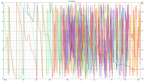
Two files contain 10 measurements made under the same conditions after 1 minute. This is about floating delay.
The total variation in the delay figures across all 10 measurements is 2.7 us, to express that as a distance sound travels it is just under 1 mm. You consider that a large variation in a measurement made at 2.5 m? And that is despite some of the measurements being made in the presence of significantly higher background noise than others and all the measurements suffering from high background noise levels at 2.7 kHz and its harmonics. It looks like very good performance to me.
It concerns also my case? When the microphone is in front of tweeter, and its and others speakers measurements make from one position, from one point? Thus the distance from a microphone up to tweeter is not equal to distance from a microphone up to the midrange and up to the others speakers.
The distances to the drivers will not be the same when you listen either. If you are using 2.5 m as the measurement distance because that is the distance at which he drivers should integrate then make the measurement with the mic so that it aligns with the intended listening position height on the speaker.
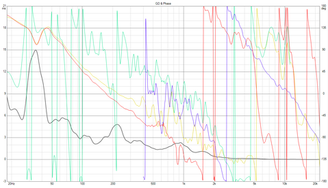
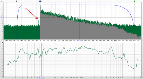
Measuring at that distance means the measurement contains a lot of reflections. That will make the responses, both magnitude and phase, difficult to interpret. You could reduce the impulse response windows to gate out the reflections, but there is a big reflection (63% of the peak so only 4 dB down) at just 1.21 ms and another (35% of the peak, so 9dB down) at 13.1 ms. If you gate out the 1.21 ms reflection the response will only have about 900 Hz resolution and nothing below 900 Hz. To measure the speaker you need to move it as far as possible from all surfaces, such as in the middle of a large room, preferably with a high ceiling and raised off the floor, or moved outside. A frequency-dependent window can help reduce the impact of reflections without sacrificing as much frequency resolution, there is an option on the
IR windows dialog to apply a frequency dependent window.
The measurements also show a significant peak (23 dB down) 7.35 ms before the measurement itself, which corresponds to the timing difference of the loopback connection. That suggests there is a lot of crosstalk between the measurement and loopback channels. That might be from the wiring arrangements, in which case you could improve it by keeping the wiring for the input channels away from each other, or it might be in the interface, which would be more difficult to fix. It is rare to see such high levels of crosstalk.