Measuring and designing for time delay between drivers of a 3 way speaker

selim

Registered
Thread Starter
Joined
Dec 22, 2020
Messages
21
More  
Preamp, Processor or Receiver
minidsp
Hi,

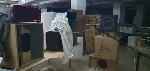
I have a 3 way active speaker that I've built. The midrange compression driver is in the back, mounted on a horn, the woofer is in front of it, and the tweeter is on the front of the speaker. To time-align these drivers, I need to input the delay values in the DSP of the plate amp. How can I measure the delay of the sound from the woofer and tweeter with respect to the midrange driver, as they arrive to the mic? Thanks in advance.

Selim
 

sm52

Member
Joined
Mar 14, 2019
Messages
892
Select the asio driver in preferences/soundcard, your output device, output and reference output should be different. If the driver is java, the output device name must contain excl. The output and reference output must be different. Connect the wires of the reference output channel to the second tweeter (not the one that will be measured). You will connect the output channel wires one by one to the drivers being measured. In the measurement window, select acoustic timing reference. Next, measure the three drivers in turn, without changing any settings. After three measurements, go to the overlays/impuls tab. Below, mark all measurements with birds. Based on the impulse peaks, determine the time distances between the drivers.
 

selim

Registered
Thread Starter
Joined
Dec 22, 2020
Messages
21
More  
Preamp, Processor or Receiver
minidsp
Hi, thank you for your reply. I tried posting a reply soon after yours, but I had forgotten to click post. :) Sorry about that:

OK, I did that. In fact I even found the delays in the measurement tabs like the following:
"Delay 0.7030 ms (241 mm, 9.49 in)
using estimated IR delay relative to Acoustic reference played from L with no timing offset"
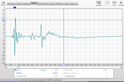
then I adjusted the delay settings on my DSP to time align the drivers and did a sweep. The crossover points look much better, and then I inverted the phase on one of the drivers to see if it would create a null at xo point. Sure enough it did. Then I checked the impulse graph and to my surprise, instead of seeing a single impulse (since they are now supposed to be aligned), I still see three distinct driver impulses. Picture attached. Shouldn't be a single impulse?
 

Attachments

  • Screen Shot 2023-09-22 at 20.48.42.png
    Screen Shot 2023-09-22 at 20.48.42.png
    28.4 KB · Views: 25

sm52

Member
Joined
Mar 14, 2019
Messages
892
If the three impulses are correctly timed, there should be one impulse when working together. If there are measurements of the three drivers before correction, I can take a look. Attach mdat file here.
 

selim

Registered
Thread Starter
Joined
Dec 22, 2020
Messages
21
More  
Preamp, Processor or Receiver
minidsp
I think the impulse is ok now. I think I made a mistake measuring earlier. The thing I don't understand is the impulse before the 0 point. Is that the source signal itself, and the 0-point impulse the actual response? File attached.
 

Attachments

  • FR and individual drivers crossed over.mdat
    6.1 MB · Views: 22

selim

Registered
Thread Starter
Joined
Dec 22, 2020
Messages
21
More  
Preamp, Processor or Receiver
minidsp
I still see a big notch at the crossover point. I guess the timing isn't quite right. I'm timing the drivers with an external reference speaker and doing the whole thing again.
 

jtalden

Senior Member
Joined
May 22, 2017
Messages
888
Location
Arizona, USA
More  
Preamp, Processor or Receiver
Marantz AV7705 Pre/Pro
Main Amp
VTV 6 chnl NC252MP P-amp x 2
Additional Amp
Behringer DCX2496 x 2
Universal / Blu-ray / CD Player
OPPO BDP-103 Universal Player
Front Speakers
DIY SEAS H1456/H1212 Spkr x 5
Subwoofers
DIY JBL 2235H 15" SW x 2
Video Display Device
JVC DLA-X790R
Screen
Da-Lite Da-Snap 39105V - 92"
There is excessive SPL overlap of the TW and Mid. It appears that XO was not active during the measurements.

Setup
> Mic should be located on the listening axis to the midpoint between the TW and Mid
> Both XOs need to be active for the measurements
> Acoustic timing is needed.

The REW alignment tool can then be used to select favorable delay timings.

temp.jpg
 

sm52

Member
Joined
Mar 14, 2019
Messages
892
It is better to show measurements before correction. On the general measurement, the additional impulse is a separate tweeter. It should not be in the general measurement. The REW version is newer now. Much has been improved and corrected.
 

selim

Registered
Thread Starter
Joined
Dec 22, 2020
Messages
21
More  
Preamp, Processor or Receiver
minidsp
OK, I measured each driver with and without filters XO's on. I also did several full-range sweeps. I think the drivers are time-aligned now. At least they have the same delay value with respect to the reference speaker. Also, there is still a notch at around 800Hz, the crossover freq between the woofer and mid. I've tried many things but it doesn't go away. Also as per jtalden's suggestion, I tried to reduce the overlap between mid and tw by crossing the tweeter with a higher-order high-pass. I have included measurements with timing data. Am I on the right track? What can I improve? And generally, how is the full-range response graph? How can I remedy the notch at 800Hz?

I used a side speaker for timing ref impulse.
 

Attachments

  • 20230925_204252.jpg
    20230925_204252.jpg
    163.7 KB · Views: 24

selim

Registered
Thread Starter
Joined
Dec 22, 2020
Messages
21
More  
Preamp, Processor or Receiver
minidsp
I don't see the mdat file I uploaded in my previous post. I try to post it here again.
 

selim

Registered
Thread Starter
Joined
Dec 22, 2020
Messages
21
More  
Preamp, Processor or Receiver
minidsp
Let's try it zipped. It's 23MB. Maybe too big for here.
 

sm52

Member
Joined
Mar 14, 2019
Messages
892
Save half of the measurements as a separate file. Then the second half as a separate file.
 

selim

Registered
Thread Starter
Joined
Dec 22, 2020
Messages
21
More  
Preamp, Processor or Receiver
minidsp
Here is the first half of the measurements.
 

Attachments

  • FR to send1.mdat
    14.8 MB · Views: 17

selim

Registered
Thread Starter
Joined
Dec 22, 2020
Messages
21
More  
Preamp, Processor or Receiver
minidsp
And the second half. Thanks sm52
 

Attachments

  • FR to send2.mdat
    14.1 MB · Views: 16

jtalden

Senior Member
Joined
May 22, 2017
Messages
888
Location
Arizona, USA
More  
Preamp, Processor or Receiver
Marantz AV7705 Pre/Pro
Main Amp
VTV 6 chnl NC252MP P-amp x 2
Additional Amp
Behringer DCX2496 x 2
Universal / Blu-ray / CD Player
OPPO BDP-103 Universal Player
Front Speakers
DIY SEAS H1456/H1212 Spkr x 5
Subwoofers
DIY JBL 2235H 15" SW x 2
Video Display Device
JVC DLA-X790R
Screen
Da-Lite Da-Snap 39105V - 92"
selim, I used your "send1" mdat file measurements 3, 6, 7 for my analysis. These measurements represent the W, M, T with both XOs active. These were copied in my file below as the first 3 measurements. The measurements below those 3 represent the analysis process.

For a conventional timing alignment, the following delay timing changes are needed (changes to the actual delays used for these measurements):

Tweeter = Reference (no change)
Midrange = 0.01 ms and polarity inverted.
Woofer = 0.23 ms and current polarity.

Notes:
The midrange delay change is trivial. Its polarity just needs to be inverted. Also - with an XO at 10 kHz any slight change up or down in the listening axis will significantly impact the timing and thus SPL so the delay timing is really not a significant concern in this case.

The woofer delay should target 0.22 ms greater than the midrange setting as listed. It is not as sensitive as to minor up and down differences, but the relatively large offset from the horn will narrow the vertical dispersion lobe as well.

The bottom measurement in the attached file is the overall calculated response. This measurement can be imported into your mdat to compare SPL, phase, etc. with some of your overall measurements.

SPL.jpg


Phase.jpg


Step.jpg
 

Attachments

  • ja3.mdat
    5.4 MB · Views: 13

sm52

Member
Joined
Mar 14, 2019
Messages
892
Based on measurements 7,8,9 of the second file, I would make the delay for the tweeter 1.2 ms, for the woofer 0.14 ms. I would divide the woofer and mid at 850 Hz, you can try dividing the mid and tweeter from 8 kHz to 12 kHz. The order of the filters, the smaller, the better. The polarity is positive for everyone. Perhaps the mid at the top can be left as is, without a filter, and for the tweeter a second order can be made.
 

selim

Registered
Thread Starter
Joined
Dec 22, 2020
Messages
21
More  
Preamp, Processor or Receiver
minidsp
Thank you JT, I will try your settings and measure and post it here. I'm curious, why reverse the mid's polarity? My XO's 8th order, and I don't think I connected the mid with the wrong polarities. It must be something you see in the phase graph. Can you please elaborate?
 
Last edited:

selim

Registered
Thread Starter
Joined
Dec 22, 2020
Messages
21
More  
Preamp, Processor or Receiver
minidsp
Thank you sm52. The woofer and mid are crossed at 800 now with 8th order L-R (the woofer has breakup after around 1k. So I thought it best to do a sharp cutoff. Is that a bad idea? The tweeter is crossed at 10k. The mid has no upper XO. Also there is a wide cut filter around 280Hz to flatten the woofer response, as well as a 4dB boost at 4500 for the mid.
 

sm52

Member
Joined
Mar 14, 2019
Messages
892
Too much filter slope can make a bad sound. It is better to solve all issues in a maximum of 2nd order. If there is no reason to increase the order.
 

selim

Registered
Thread Starter
Joined
Dec 22, 2020
Messages
21
More  
Preamp, Processor or Receiver
minidsp
I tried to pick a high enough XO point to protect the compression driver (Beyma CP380m), and low enough to not get into the breakup zone of the woofer. The horn is an Altec 511b that goes down to 500. 2nd order seems to go way into the breakup zone of the woofer and is quite low for the CD although the horn has a lot of gain so the CD will probably not need a lot of power. Isn't less XO overlap good for a wider lobe?
 

sm52

Member
Joined
Mar 14, 2019
Messages
892
It's just worth checking all the options. You will hear what is best.
 

selim

Registered
Thread Starter
Joined
Dec 22, 2020
Messages
21
More  
Preamp, Processor or Receiver
minidsp
OK, I will try second order as well.
 

selim

Registered
Thread Starter
Joined
Dec 22, 2020
Messages
21
More  
Preamp, Processor or Receiver
minidsp
JT, I reversed the polarity of the mid. Applied the timing change. The notch is gone. And my measured graph looks almost exactly as yours: A plus B FR Aligned. Thank you. The speaker sounds pretty good right now. Do you have any comments on the overall response graph and what you think could be better?
 

jtalden

Senior Member
Joined
May 22, 2017
Messages
888
Location
Arizona, USA
More  
Preamp, Processor or Receiver
Marantz AV7705 Pre/Pro
Main Amp
VTV 6 chnl NC252MP P-amp x 2
Additional Amp
Behringer DCX2496 x 2
Universal / Blu-ray / CD Player
OPPO BDP-103 Universal Player
Front Speakers
DIY SEAS H1456/H1212 Spkr x 5
Subwoofers
DIY JBL 2235H 15" SW x 2
Video Display Device
JVC DLA-X790R
Screen
Da-Lite Da-Snap 39105V - 92"
selm,
The conventional objective for each XO is to have the phase of the 2 drivers overlap, i.e., closely track each other throughout the XO range. This has several technical benefits regarding the XO range of frequencies:
  • The SPL is maximally supported
  • The sound from both drivers will arrive at the mic/LP at the same time for each frequency
  • The horizontal off angle SPL is more uniform
  • The main frontal lobe of sound is maximally large and not shifting up or down
The room and EQ are much bigger influences on the SPL and thus has more impact on sound quality, the practical benefit of this alignment is thus not easily demonstrated. It is considered adequate to adjust the delay to provide a phase crossing point at the XO midpoint. That situation also provides similar SPL support.

So, a driver's polarity is best chosen to provide the closest phase tracking throughout the XO range, but so as long favorable SPL is achieved it is not critical.

From the mdat I posted:

10k XO phase tracking.jpg


800 XO phase tracking.jpg
 
Top Bottom