Capacitors, inductors and resistors measurements

Cristianolo

New Member
Thread Starter
Joined
Dec 14, 2018
Messages
24
Hi all.
Is there some tutorial about the right way to measure passive components using REW?
 

John Mulcahy

REW Author
Joined
Apr 3, 2017
Messages
7,212
Components can be measured in the same way as any other load. For inductors and capacitors you can read the equivalent series and parallel impedance values from the box in the lower left corner of the Impedance and phase graph, there will be some variation with frequency.
 

Shonver

Registered
Joined
May 5, 2020
Messages
22
Given that there is variation with frequency regarding the reported component value, what is a reliable way to determine the actual value? The following is some data from the measurement of a particular air core inductor:

f(Hz), R, L(uH)
3, 0.377, 693
10, 0.381, 908
30, 0.379, 905
100, 0.389, 903
300, 0.385, 908
1k, 0.434, 907
3k, 0.859, 905
10k, 5.3, 883

Rse (measured with a DMM): 0.39R

I suppose one can make an informed guess based on the measured series resistance. My meter has 0.01R resolution, but I think that most DIYers' DMMs would read that as 0.4R.

90% = 0.36
95% = 0.38
100% = 0.4
105% = 0.42
110% = 0.44

If one were to tabulate the data as I did, one can visually identify similar data (5 sets; 10Hz to 1kHz) and derive an average for those points. (At 3Hz, the L value begins to deviate and at 3kHz and 10kHz the R value deviates from the central grouping).

Based on this approach, one derives a value of 0.394R, 906.2uH (averaged; 10Hz to 1kHz)

I suspect that this problem is typical only for inductors and not so much for capacitors (my reference 1.003uF capacitor displayed the same value -1uF- all along its curve). Without a ohmmeter at hand, one might not have a basis for judging the (probable) correct value.

What to do?
 

Shonver

Registered
Joined
May 5, 2020
Messages
22
@John Mulcahy

I have thought a bit about this, and have some suggestions (new feature request):

1. When the cross-hair on the impedance curve is displaying the component values at that point, highlight the section of the curve that matches this value. Allow the user to specify limits for the match (say, within 1%, 2%, 5%, etc.).

and/or

2. Allow the user to seed the L measurement by inputting the DC resistance (if it is known), and base L calculation on this value. Highlight section of curve that holds true for the derived values (again, with tolerance limits).
 

John Mulcahy

REW Author
Joined
Apr 3, 2017
Messages
7,212
REW is measuring impedance rather than trying to be an LCR meter. Typically an LCR meter will show values at the chosen test frequency - the equivalent on the REW impedance plot is simply placing the cursor at that frequency and reading the series and parallel impedance values from the box in the corner of the graph. An alternative view would be to plot the series or parallel capacitance, inductance and resistance values separately versus frequency, but it doesn't really seem worth the effort given that values at frequencies of interest can already be read directly from the impedance plot.
 

Shonver

Registered
Joined
May 5, 2020
Messages
22
I gathered as much.

I couldn't help but spot the potential of having such a feature, as that would complete it (REW) as a measurement suite for loudspeaker design. Getting the inductor series resistance right is a necessity in passive crossovers, especially when in series with the woofer. My suggestion was made for the purpose of helping the user to identify over what range of frequencies (not single frequency) the derived L&R values are valid.
 

John Mulcahy

REW Author
Joined
Apr 3, 2017
Messages
7,212
There isn't a single value for the resistive component of an inductor's impedance, it increases with frequency (principally due to skin effect). Even at lower frequencies the variation may be significant for large gauge wire. The values shown are the actual components of the impedance at the selected frequency, there isn't a question over their validity, only their accuracy, which reduces as impedance increases.
 

Shonver

Registered
Joined
May 5, 2020
Messages
22
So when I refer to the frequency range (band) over which the indicated value is valid, I am inferring that there is a band of interest - to the user. And more to the point of validation: because the indicated values vary with frequency, one would want to make the best decision when selecting a reading along the curve when using the tool for measuring the value of an inductor. Crossover design simulators only use one pair of L & R values, and likewise inductors are spec'ed using these two parameters.

I cannot disagree with your explanation above; it is the reason why the measured graph would not fit an ideal L+R curve. I am suggesting that there must be pair of L&R values that describes a large part of the curve with tolerance (the % variances I suggested); this is obvious when eyeballing the data points I sampled above. Computer-based applications that measure passive components can do better than measuring a single frequency point, (some inductance meters give you a choice of 2 sampling frequencies). One method that I am aware of is to use curve-fitting: comparing the measured curve to idealised L+R values, the result being the best-fit values. Predictably, changing the start and end frequencies yields different values, thus the practice of choosing a "band of interest" (perhaps the two octaves spanning the intended crossover region).

Actually, I don't mind doing it manually as I did above. It seems to yield good results (to my expectations). I do think that adding "passive component measurement" to REW's already excellent box of tricks would be well received.
 

AudioCAT

Registered
Joined
May 4, 2018
Messages
15
There isn't a single value for the resistive component of an inductor's impedance, it increases with frequency (principally due to skin effect). Even at lower frequencies the variation may be significant for large gauge wire. The values shown are the actual components of the impedance at the selected frequency, there isn't a question over their validity, only their accuracy, which reduces as impedance increases.
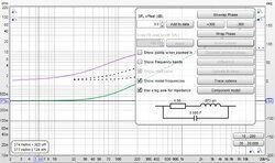
The impedance measurement function has actually been able to measure inductors and capacitors more accurately, at least in large frequency bands, especially the Rs of the inductor and the ESR of the capacitor can be displayed in the lower left corner.
A luxurious idea, since the series relationship is already very accurate, it would be better if the curve can also be displayed through the check box, which is very helpful for amateurs to build speaker crossovers, and it is very convenient to filter electronic components .
Because different inductors, such as air cores, ferrite cores, and silicon steel cores, have very different Rs values, it is undoubtedly very pleasant to choose inductors if the curve can be displayed. :yay:
31533
 

John Mulcahy

REW Author
Joined
Apr 3, 2017
Messages
7,212
OK, you have collectively talked me into it :)

For the next build I have added a Component model button to the Impedance & phase graph controls. The button is only enabled for impedance measurements of inductors or capacitors. REW identifies the measurement as being of a capacitor if the phase at 20 Hz (or the start of the measurement, if higher) is below -60 degrees, or an inductor if the phase at 20 kHz (or the end of the measurement, if lower) is above 60 degrees. For those measurements pressing the button will carry out a curve fit over the range from 20 Hz to 20 kHz (or the measurement range if smaller) to derive equivalent circuit component values. For capacitors the equivalent circuit is a series combination of a resistor (the ESR), a capacitor with a parallel resistor (leakage) and an inductor (likely to be very small at audio frequencies, not shown if less than 1 nH). For inductors the circuit is a series resistor and inductor with a parallel capacitor. The equivalent circuit is shown below the button. The equivalent circuit impedance is shown as a dashed line overlaying the measured impedance.

31550


31546
 
Last edited:
Joined
Feb 8, 2018
Messages
279
Location
Italy
Fantastic John, this feature is really very useful for those who design cross-over because it allows you to know the real characteristics of the components you use.
Fantastic !!!!
 

John Mulcahy

REW Author
Joined
Apr 3, 2017
Messages
7,212
I have added a leakage resistor to the capacitor model, updated the post above to show it. Very low on the old electrolytic I measured, more typically in the 10's to 100's of kohm.
 

AudioCAT

Registered
Joined
May 4, 2018
Messages
15
Fantastic! :jump:
I was very, very happy to hear the news. This is really great, thank you very much John
 

Shonver

Registered
Joined
May 5, 2020
Messages
22
I have been trying out the component feature. This is what I found:

I measured a couple of inductors. I'll discuss one of them, though the same issue was observed for both. This inductor has a measured (DMM) series resistance of 0.34R. The measured curve (green) is in agreement with this, since it is in the same ballpark below 10Hz. REW's Component Model reports a value of 1.5R, 874uH. Placing the cursor at 5.56Hz (in the region where series resistance is similar to the DMM's), the inductance reads 0.374R, 923uH. The dashed line that REW plots for the derived inductance begins to deviate from the measured curve below 800Hz, flattens to about 1.5 R and stops at 20Hz.

REWz1.jpg


I evaluated the effect that these two values (1.5R, 874uH and 0.374R, 923uH) would have in a crossover with nominal load of 8R.

VituixCAD Filter.jpg


Observation: There is a 1dB difference in SPL between the two values.

Conclusion:
(1) REW is capable of measuring inductance down to very low frequencies.
(2) The series resistance of an inductor can have a significant effect in a crossover and may produce SPL errors if not correctly measured. In more complex circuits the effects can be accumulative.

Thoughts: It is possible that currently REW only models the passive component down to 20Hz. It seems necessary to extend this range as low as feasible in order to correctly derive series resistance of an inductor and perhaps the model could be weighted for accuracy towards the lower frequencies for this purpose.

I have attached the inductor's mdat file here.
 

Attachments

  • Inductor1 May 13.mdat
    1.9 MB · Views: 14
  • 31610-10b18aa05caf11a55a5729b4773c2d3b.jpg
    31610-10b18aa05caf11a55a5729b4773c2d3b.jpg
    10 KB · Views: 54
  • 31609-e9df24e053ccebe364bc2ea29e2fab41.jpg
    31609-e9df24e053ccebe364bc2ea29e2fab41.jpg
    8 KB · Views: 54
Last edited:

John Mulcahy

REW Author
Joined
Apr 3, 2017
Messages
7,212
I have been trying out the component feature.
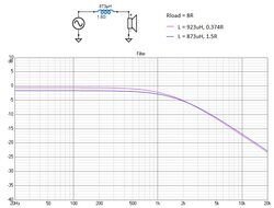
Thanks. I was rather limited in the range of inductors I had available to test with, but the fit is easily adapted to better manage larger values. If you can provide measurements of other large inductors that would be helpful.

31615
 

Shonver

Registered
Joined
May 5, 2020
Messages
22
I don't have the best variety available. Trust these will be of use.
 

Attachments

  • 0.61mH-ish.mdat
    1.9 MB · Views: 14
  • 1.16mH-ish.mdat
    1.9 MB · Views: 13
  • 2.8mH-ish.mdat
    1.9 MB · Views: 15
  • 4.9mH-ish.mdat
    1.9 MB · Views: 17

John Mulcahy

REW Author
Joined
Apr 3, 2017
Messages
7,212
That's great, thanks. Can you tell me anything about the inductors themselves, how they are constructed, for example? The 4.9 mH, 1 mH and 0.61 mH have good fits to an R+L model, but the 1.16 mH and 2.8 mH have somewhat odd phase responses and do not fit well, wondering why that might be.

Edit: added the plots.

1589471607332.png 1589471638260.png 1589471657962.png 1589471689218.png 1589471728558.png
 
Last edited:

Shonver

Registered
Joined
May 5, 2020
Messages
22
Inductor1 May 13.mdat - air core; hand wound

AC3.jpg


0.61mH-ish.mdat - small laminated core; tight, neatly wound

LC1.jpg


1.16mH-ish.mdat - larger laminated core; tight, neatly wound
2.8mH-ish.mdat - larger laminated core; tight, neatly wound

LC2.jpg


4.9mH-ish.mdat - air core; hand wound

AC2.jpg
 

John Mulcahy

REW Author
Joined
Apr 3, 2017
Messages
7,212
Something to do with the laminated cores in the 1.16 mH and 2.81 mH inductors, perhaps. I have revised the inductor model to drop the winding capacitance element, which seems negligible at audio frequencies, and instead add a shunt R to allow for core losses. That has improved the fit a lot.

31632


31633


31634


31635


31636
 
Joined
Feb 8, 2018
Messages
279
Location
Italy
John wants to make REW become the reference software in electroacoustics and I think he is succeeding, my concern is that if it continues to increase its potential the day will come that I will no longer be able to use it with the Raspberry and I will no longer be able to assemble an audio analyzer all in one with open source hardware and software and I will necessarily have to use proprietary x86-based cpu hardware.:frown:
Anyway thanks John, superlative work !!;)
 

Shonver

Registered
Joined
May 5, 2020
Messages
22
John wants to make REW become the reference software in electroacoustics and I think he is succeeding, my concern is that if it continues to increase its potential the day will come that I will no longer be able to use it with the Raspberry and I will no longer be able to assemble an audio analyzer all in one with open source hardware and software and I will necessarily have to use proprietary x86-based cpu hardware.:frown:
Anyway thanks John, superlative work !!;)

This latest feature really rounds off REW as a complete measurement system (at least, to my requirements). I have had REW installed on my PC for some years, but rarely used it. The improved calibration with lead compensation raised its performance and finally converted me.

I saw your outstanding work with the Raspberry Pi. I would love to have a standalone measuring setup. Even better if it is portable. At the moment my measurement setup comprises an old desktop PC, external audio interface (M-Audio Firewire 410), a dedicated audio amplifier and an interface box.
 

Breeman

Member
Joined
Jan 9, 2019
Messages
151
John wants to make REW become the reference software in electroacoustics and I think he is succeeding, my concern is that if it continues to increase its potential the day will come that I will no longer be able to use it with the Raspberry and I will no longer be able to assemble an audio analyzer all in one with open source hardware and software and I will necessarily have to use proprietary x86-based cpu hardware.:frown:
Anyway thanks John, superlative work !!;)
I agree entirely with your sentiment. I have not once used my CLIO pocket ever since I started to actively use REW. It's user friendly interface, flexibility and feature layout are just top notch. It already has bucket a load of feature capabilities and John keeps adding more:). I think what also gives it the edge is that John seems to have his ear on the ground about how users actually use his software and he adapts it accordingly, he support on issues raised is unparralled, even compared to paid-for software in my opinion. I cannot thank him enough.
 
Top Bottom