Calibration Ruins Impedance Measurements

bangiel

Registered
Thread Starter
Joined
Apr 7, 2021
Messages
16
Hello,

I'm conducting impedance measurements for several guitar speaker cabinets I have in my possession. The problem, in short, is that going through the calibration steps ruins my results.
  • Speaker Cabinet is 8 Ohm
  • Sense Resistor is 100 Ohm
  • Reference Resistor is 10 Ohm
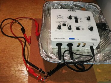
  • Audio Interface is a Motu M4 (1M Ohm Input Impedance)
  • I am using speaker cables for all connections (LiveWire Elites)

Here is a no-calibration measurement of a Mesa/Boogie Traditional 4x12. It looks about right for the most part. Could we make it more accurate? Let's see.

44795


Here are my calibration results--

Open Circuit

44796


Short Circuit

44797


Open and Short Circuit (just trying to be thorough)

44798


Reference Resistor

44799


And finally, the fully-calibrated measurement...

44801


Well that doesn't look right at all... The No Cal measurement leads me to believe I am on the right track. I am messing something up somewhere during the Calibration process. Any ideas what that might be?
 

trobbins

Member
VIP Supporter
Joined
Nov 26, 2017
Messages
121
Location
Australia
Perhaps just to go through some practical steps that could affect an outcome:
Have you tried to adjust the Rsense to 100.8.
Have you stepped the Settings for Length - I use 4M.
Are you using screened leads for signal output, and the two inputs, and using a small metal film sense resistor with the hot connections to each end with minimal unscreened length, and all screens neatly soldered next to the sense resistor.
Are you using a relatively short set of DUT connection leads with good crocodile clips to connect to your DUT/reference resistor that also clip to each other for the short test.
Is the reference resistor a small metal film resistor.
Are you using ASIO driver with at least 96kHz sampling that you know performs ok.
 

John Mulcahy

REW Author
Joined
Apr 3, 2017
Messages
7,212
The no cal measurement is very, very noisy. The short circuit measurement is wrong, it should be measuring close to zero, since the only impedance should be the test leads that are shorted together. Since that is wrong everything after it will be wrong. Make sure the input channel selection is the right way around and the jig is wired correctly.
 

jschwender

Member
Joined
Mar 16, 2021
Messages
140
Location
GERMANY
More  
Front Speakers
Nubert digital pro
Other Speakers or Equipment
Philips dss940
The Motu is an excellent choice. It can provide very high output level of +16dBu, and there is no specification for an output impedance. Your sense Resistor of 100 Ohm may cause current limit clipping on your output, as it is certainly made for higher impedance. You may choose an output level more like 1 V and see if it different. The best choice anyway is to use an amplifier after the output and cables as short as possible. That enables impedance measurement to very low and very high values with very low noise. Keep in mind that the speakers same time work as microphone and you get acoustical noise and wall reflections feed back into your measurement. I put the speaker right in front of an open window, 3rd floor, this way reflections are close to zero.
 

Attachments

  • Kupferrohr_Impedanz1.jpg
    Kupferrohr_Impedanz1.jpg
    208.8 KB · Views: 30

bangiel

Registered
Thread Starter
Joined
Apr 7, 2021
Messages
16
Perhaps just to go through some practical steps that could affect an outcome:
Have you tried to adjust the Rsense to 100.8.
Have you stepped the Settings for Length - I use 4M.
Are you using screened leads for signal output, and the two inputs, and using a small metal film sense resistor with the hot connections to each end with minimal unscreened length, and all screens neatly soldered next to the sense resistor.
Are you using a relatively short set of DUT connection leads with good crocodile clips to connect to your DUT/reference resistor that also clip to each other for the short test.
Is the reference resistor a small metal film resistor.
Are you using ASIO driver with at least 96kHz sampling that you know performs ok.
I've used a couple different sense resistors. 100Ohm was my first try, and the results were the same.
 

bangiel

Registered
Thread Starter
Joined
Apr 7, 2021
Messages
16
The no cal measurement is very, very noisy. The short circuit measurement is wrong, it should be measuring close to zero, since the only impedance should be the test leads that are shorted together. Since that is wrong everything after it will be wrong. Make sure the input channel selection is the right way around and the jig is wired correctly.
This is helpful, thank you. I'll check the jig again.
 

bangiel

Registered
Thread Starter
Joined
Apr 7, 2021
Messages
16
The no cal measurement is very, very noisy. The short circuit measurement is wrong, it should be measuring close to zero, since the only impedance should be the test leads that are shorted together. Since that is wrong everything after it will be wrong. Make sure the input channel selection is the right way around and the jig is wired correctly.
I rebuilt my jig, and I'm still not getting proper short ckt results. In fact, I removed the jig entirely from the equation, and the short ckt measurement is still messed up. I shorted the headphone and test lead connections as such:
45020


And I'm still seeing a non-zero impedance:
45021


What could I be doing wrong?
 

John Mulcahy

REW Author
Joined
Apr 3, 2017
Messages
7,212
For the short circuit measurement the measurement input is shorted to ground, not to the output. The sense resistor remains in circuit. Per the connection diagram, it corresponds to a short across the driver connections, in similar fashion to the open circuit measurement which corresponds to no driver connected.

45025
 

bangiel

Registered
Thread Starter
Joined
Apr 7, 2021
Messages
16
For the short circuit measurement the measurement input is shorted to ground, not to the output. The sense resistor remains in circuit. Per the connection diagram, it corresponds to a short across the driver connections, in similar fashion to the open circuit measurement which corresponds to no driver connected.

View attachment 45025
Understood. I will try that.
 

bangiel

Registered
Thread Starter
Joined
Apr 7, 2021
Messages
16
For the short circuit measurement the measurement input is shorted to ground, not to the output. The sense resistor remains in circuit. Per the connection diagram, it corresponds to a short across the driver connections, in similar fashion to the open circuit measurement which corresponds to no driver connected.

This fixed my issue. I misunderstood the short circuit cal step. I'm getting what look to be good measurements, however:
  • They don't look that different from the no-cal measurements
  • There's still a good bit of noise - the measurement isn't super clean by any means
 

John Mulcahy

REW Author
Joined
Apr 3, 2017
Messages
7,212
  • Drivers are microphonic, the measuring environment needs to be quiet
  • Don't measure at too high a level, typically want around 100 mV at the driver
  • Use long sweeps
  • Use REW's noise filter
  • Use a source with a low output impedance, headphone outputs usually have lower impedance than line outputs
 

bangiel

Registered
Thread Starter
Joined
Apr 7, 2021
Messages
16
  • Drivers are microphonic, the measuring environment needs to be quiet
  • Don't measure at too high a level, typically want around 100 mV at the driver
  • Use long sweeps
  • Use REW's noise filter
  • Use a source with a low output impedance, headphone outputs usually have lower impedance than line outputs
  • NIOSH app is measuring 30-33db[A] in my space - it's pretty quiet
  • I tried with the HP output at full and half with no difference
  • I tried 1M sweep and 4M sweep with no difference
  • I tried no filter and high filter with no difference
  • I am using the HP output
 

bangiel

Registered
Thread Starter
Joined
Apr 7, 2021
Messages
16
Then the driver and the cabinet may be the ones producing the nasty resonances.
I have 5 speaker cabinets and all are producing similarly noisy plots. The only thing that makes the plots look "pretty" is smoothing (surprise, surprise, right?).

I'm not saying REW is to blame, obviously. The common thread is my audio interface / speaker cables / jig (granted, I've tested with two jigs by this point). My room could be an electrically noisy mess for all I know, as well.

Interestingly enough, with the HP volume cut, the input gain on my Motu is up around noon, and I can see the input signal bouncing slightly with every minor noise I make--even typing this. There seems to be a balance to be struck there--output volume low enough to hit your 100mV recommendation, but high enough to not require a ton of gain. That said, I didn't measure any meaningful differences, so I may be overthinking that.
 

bangiel

Registered
Thread Starter
Joined
Apr 7, 2021
Messages
16
It's now occurring to me how much noisier my current measurements are vs the ones I originally posted. Oddly enough, nothing about my set up has changed (testing the original jig yields the same results). I have no idea what's introducing all that high freq noise all of the sudden.
 

John Mulcahy

REW Author
Joined
Apr 3, 2017
Messages
7,212
You can clear the cal and measure again to see if any of that is embedded from the cal measurements.
 

bangiel

Registered
Thread Starter
Joined
Apr 7, 2021
Messages
16
You can clear the cal and measure again to see if any of that is embedded from the cal measurements.
The noise is still present after clearing the calibration. What a weird turn of events.

Truthfully, all I wanted to derive from this was the resonant frequency of the driver in the enclosure. I can glean that information, even from a noisy plot.
 

jschwender

Member
Joined
Mar 16, 2021
Messages
140
Location
GERMANY
More  
Front Speakers
Nubert digital pro
Other Speakers or Equipment
Philips dss940
Looks odd. If i take that plot seriously as a speaker impedance, such multiple resonance peaks are usually caused by damages on a speaker.
 

bangiel

Registered
Thread Starter
Joined
Apr 7, 2021
Messages
16
Looks odd. If i take that plot seriously as a speaker impedance, such multiple resonance peaks are usually caused by damages on a speaker.
I’m pretty confident in the fit and function of the speakers and the enclosures. Of all my potential issues, I don’t believe this is one of them.
 

sam_adams

Member
Joined
May 23, 2017
Messages
285
Don't measure at too high a level, typically want around 100 mV at the driver

As always, @John Mulcahy is correct here. With a low load resistance,—even on the headphone output—too high a signal level may cause the headphone output to distort terribly.

I tried with the HP output at full and half with no difference

If you have access to an oscilloscope that has peak and RMS measuring capabilities, you can check the headphone output signal with the load to see what the max level you can apply without the output distorting. Of course, different devices will have different limits and you may find that you can't output more than about 1 Vrms into a load resistance that low. You can then adjust your level down accordingly or try a higher sense resistor as John recommends in the REW help.

If you measure the driver in free air, don't place it on a table or flat surface, hang it from something so there are no close reflections from any surface that could be picked up by the speaker. If measuring in an enclosure, you may need to add some batting to reduce internal reflections.
 

trobbins

Member
VIP Supporter
Joined
Nov 26, 2017
Messages
121
Location
Australia
Can you show a photo of your measurement setup when taking the 10 ohm resistor plot? Your result seems very noisy, and that may be related to your connectors/sockets and cables and how you connect the 10R and whether you are in a noisy environment. I use a custom impedance measurement jig (shown below), with short lengths of shielded cable coming from the USB soundcard, and the shielded cable cut and only opened up enough for the sense resistor to be soldered to and to then be wired to 4mm sockets so that I can use short test leads with crocodile ends to connect to a DUT. I have to turn off one LED bench lamp that uses a switchmode supply, as it is too close. All the calibration tests are done with the test leads and clips in the same position, and the only changes are done at the crocodile ends to either short them or connect in the reference resistor.
 

Attachments

  • Impedance measurement rig.jpg
    Impedance measurement rig.jpg
    141.9 KB · Views: 22

bangiel

Registered
Thread Starter
Joined
Apr 7, 2021
Messages
16
I'm getting there. I turned off everything I could in the vicinity of my workspace. This is will high filtering:
45056
 
Top Bottom