Speaker Impedance measurement ,circuit and sound card output

icbcodc

New Member
Thread Starter
Joined
Apr 29, 2020
Messages
187
The high sense resistor together with the input impedance of the soundcard is making a voltage divider that is reducing the input, hence the channel difference.

Thank you John.

I will replace the RSENSE which should have been delivered today and calibrate again tomorrow.
 

jtalden

Senior Member
Joined
May 22, 2017
Messages
887
Location
Arizona, USA
More  
Preamp, Processor or Receiver
Marantz AV7705 Pre/Pro
Main Amp
VTV 6 chnl NC252MP P-amp x 2
Additional Amp
Behringer DCX2496 x 2
Universal / Blu-ray / CD Player
OPPO BDP-103 Universal Player
Front Speakers
DIY SEAS H1456/H1212 Spkr x 5
Subwoofers
DIY JBL 2235H 15" SW x 2
Video Display Device
JVC DLA-X790R
Screen
Da-Lite Da-Snap 39105V - 92"
I don't know how to do the conventional setup,sometimes I am also confused by the bad result. I just read the help file for impedance measurement and ask somebody who did that before and watch some Youtube videos.
We normally use the same channel for input and output for each purpose as:
Measurement Channel; output = R, input = R
Reference Channel; output = L, input = L
I just hadn't seen them crossed over before.
 

icbcodc

New Member
Thread Starter
Joined
Apr 29, 2020
Messages
187
We normally use the same channel for input and output for each purpose as:
Measurement Channel; output = R, input = R
Reference Channel; output = L, input = L
I just hadn't seen them crossed over before.

Sorry, It's the first time that I've measured speaker impedance using REW, I don't have an idea about normal and unnormal way.

But I just get the right result today replacing the 1000 Ohm resistor with a 100 Ohm resistor,the problem is solved.

31498
 

icbcodc

New Member
Thread Starter
Joined
Apr 29, 2020
Messages
187
The high sense resistor together with the input impedance of the soundcard is making a voltage divider that is reducing the input, hence the channel difference.

Hi John,

There is a good news. I replace the RSENSE 1000 Ohm with a 100 Ohm one, channel level problem is solved and the curve looks pretty good.

I just put all level adjustable to "Max".

Do you think I should keep this sound card for further measurement?

31499


31500


31501


31502
 

icbcodc

New Member
Thread Starter
Joined
Apr 29, 2020
Messages
187
The high sense resistor together with the input impedance of the soundcard is making a voltage divider that is reducing the input, hence the channel difference.

I did a full circuit calibaration and a first measurement of speaker impedance,maybe there is something wrong?

Level down to -6dbfs

Check level:

31503


Open circiut cal
31504


reference cal: a 49.95 ohm resistor replace the speaker load.

31505


There is no curve in the result,why?

31507


31506


refenece cal result , looks good.

31508


Ready to measure the loudspeaker impedance curve.

31509


low signal level warning message.

31510


first measurement curve,impedance is too high?

31511


Is there anything I input wrong in REW?
 

John Mulcahy

REW Author
Joined
Apr 3, 2017
Messages
7,212
You have the input channels the wrong way around, usually the input is on the R channel if you made the connections as shown in the help.
 

icbcodc

New Member
Thread Starter
Joined
Apr 29, 2020
Messages
187
We normally use the same channel for input and output for each purpose as:
Measurement Channel; output = R, input = R
Reference Channel; output = L, input = L
I just hadn't seen them crossed over before.

31512


I check the help again.

According to the help, soundcard measurement output channel should be RIGHT, input channel should be RIGHT also.

But for impedance measurement, soundcard reference output channel is not connected, input channel should be LEFT.

I know why I was wrong,I just copy the settings from the video,but I make the circuit referring the diagram in the help file, so the output channel was setting wrong to L, in my circuit it's Right output channel.

Here are the youtube video information.

In the circuit,output is LEFT.

31513


In REW, output should also be LEFT. But in my REW,output should be RIGHT channel.

31514
 

icbcodc

New Member
Thread Starter
Joined
Apr 29, 2020
Messages
187
You have the input channels the wrong way around, usually the input is on the R channel if you made the connections as shown in the help.

Yes, I'll change it.

And the Asus Xonar U3 Plus should have been kept.
 

icbcodc

New Member
Thread Starter
Joined
Apr 29, 2020
Messages
187
You have the input channels the wrong way around, usually the input is on the R channel if you made the connections as shown in the help.

Hello John,I'm back.

I modified the output channel and input channel settings in REW, and made a calibration, then I made Impedance measurements,but something is still wrong.

Could you help me?

The procedure and settings are shown below:

Max Volume, Right Channel Output and Right Channel Input( Right input channel will be connected to speaker positive in impedance measurement)

31646


Clear Calibration:

31647


Open circuit cal
Range setting: 20hz to 20000hz (Is it necessary?)
Level: 0 dBFS
Rsense value :not input (It is set to 0 by the software last step,I don't input any data)
Should I input the actual value of RSENSE which is 99.85 ohm in to Rsense field?

31648


Open circuit cal result( 99.355% of reference),looks good.

Is it a correct result?

31649


Short circuit cal
Range: 20hz to 20000hz
RSENSE: 0 (default)
RINPUT:1000 (default)
Rleads:0 (default)
31650


Impedance short circuit cal result: 113 mOhm (around),

Is it correct?
31651


Reference cal
Reference resistor value:49.85(around)
31652


The curve looks weird from 4khz to 10khz,
something wrong?

31653


Twice impedance measurements(added mass method)

31654


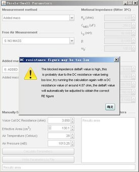
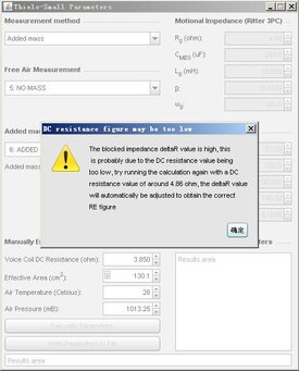
T/S Parameters error,my goodness!

Low point on impedance curve causes DC resistance too high.

Did I do anything wrong?

31655
 

John Mulcahy

REW Author
Joined
Apr 3, 2017
Messages
7,212
You have a very low value entered for the input resistance, is that figure correct? V5.20 beta 50 has a wider tolerance for level differences between channels.
 

icbcodc

New Member
Thread Starter
Joined
Apr 29, 2020
Messages
187
You have a very low value entered for the input resistance, is that figure correct? V5.20 beta 50 has a wider tolerance for level differences between channels.

Hi John,

I just input 1000 ohm as the input resistance,because I don't know how to calculate input resistance.

How can I get the correct input resistance value?

BTW, should I update Rsense after "Open circuit cal" with the value calculated by REW in the curve?
 

John Mulcahy

REW Author
Joined
Apr 3, 2017
Messages
7,212
How can I get the correct input resistance value?
Look for the figure in the specification sheet for the soundcard. If it isn't specified use 20,000.

BTW, should I update Rsense after "Open circuit cal" with the value calculated by REW in the curve?
REW is not calculating an Rsense value. Do not change it.
 

icbcodc

New Member
Thread Starter
Joined
Apr 29, 2020
Messages
187
Look for the figure in the specification sheet for the soundcard. If it isn't specified use 20,000.

REW is not calculating an Rsense value. Do not change it.

Hi John

I've tried to find out the input impedance of this SOUNDCARD (Creative Soundblaster Digital Music LX SB0271),but I failed. Even for the latest Creative soundcard, I also couldn't find the input impedance information.

Creative Soundblaster Digital Music LX ,it's more than ten year old.

31697


SB0271:

31698


So I have to input 20000 ohm into Rinput field.

Here is the result (improved) :

Open circuit cal (better)

In description, 99.877%
In curve, 99.4ohm

Which number should I refer to?
31689


Short circuit cal
In the curve, value is 182mohm,is it meaningful?
31690


Reference cal

Is there anything wrong in the curve between 2khz to 20khz?

31691


Ready for impedance measurement

31692


No mass impedance curve

Is this curve correct between 3khz to 20khz?


31693


Added mass impedance curve

Is this curve correct between 3khz to 20khz?

31694


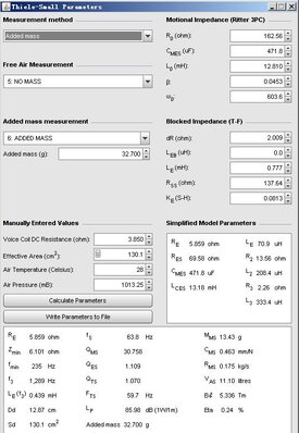
T/S parameter calculation:

a new warning message
below

31695


T/S parameter calculated:

31696


Should I keep this very old second hand soundcard (it's more than ten year old) ?
 
Last edited:

John Mulcahy

REW Author
Joined
Apr 3, 2017
Messages
7,212
In description, 99.877%
In curve, 99.4ohm

Which number should I refer to?
Those numbers are for REW, you don't have to do anything with them.

Short circuit cal
In the curve, value is 182mohm,is it meaningful?
Looks OK.

Reference cal

Is there anything wrong in the curve between 2khz to 20khz?
Yes, that noise should not be there.

Have you tried to do a normal soundcard cal with that card? Creative interfaces sometimes have unusual monitoring arrangements that cause feedback loops during measurement, it can be difficult to locate the controls to disable monitoring. See if you can get a good loopback response measurement from the card without noise.
 

icbcodc

New Member
Thread Starter
Joined
Apr 29, 2020
Messages
187
Have you tried to do a normal soundcard cal with that card? Creative interfaces sometimes have unusual monitoring arrangements that cause feedback loops during measurement, it can be difficult to locate the controls to disable monitoring. See if you can get a good loopback response measurement from the card without noise.

No.

I'm just trying to do a soundcard cal with it in latest REW,and the result looks bad and crazy.

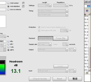
Check level

31712


Right output to Right input channel loop back

31711


bad result curve

31714


Try again, red is left input channel loopback, green is right input channel loopback.

Both are bad.

31715


circuit is like this :

I just short connect the right input to the point in front of the RSENSE,so the Rsense is bypassed.

31716


So I should get refunded and buy a new soundcard?
 

Attachments

  • 3.jpg
    3.jpg
    40 KB · Views: 12

John Mulcahy

REW Author
Joined
Apr 3, 2017
Messages
7,212
That is the appearance of monitoring being active, so some of the input is being fed back to the output. It needs to be turned off. If you go to the Windows sound Recording tab and look at the properties for the Creative input on the "Listen" tab make sure "Listen to this device" is not selected. Sometimes it is only possible to turn off monitoring using the Creative control software
 

icbcodc

New Member
Thread Starter
Joined
Apr 29, 2020
Messages
187
That is the appearance of monitoring being active, so some of the input is being fed back to the output. It needs to be turned off. If you go to the Windows sound Recording tab and look at the properties for the Creative input on the "Listen" tab make sure "Listen to this device" is not selected. Sometimes it is only possible to turn off monitoring using the Creative control software

Thank you so much, John. I found the problem.

It's not here "Listen to the device" ,it was unchecked.

31718


It's here in the Creative control panel. CMSS-3D was checked maybe by default. This caused the noise at high frequency part.

31719


I just unchecked it

31720


Normal soundcard calibration is fine.

31721


And I do a full calibration + impedance measurement + T/S parameter calculation

Open circuit cal, looks perfect.

31723


Short circuit cal, looks better

31728


Reference resistor cal, looks better.

31730


NO MASS impedance measurement,looks better.

31731


ADDED MASS, looks better.

31732


T/S PARAMETERS without any warning message.


31736


Maybe I should keep this soundcard for further measurement.
 

Attachments

  • 1.jpg
    1.jpg
    45.3 KB · Views: 11
  • 2.jpg
    2.jpg
    45.4 KB · Views: 14
  • 3.jpg
    3.jpg
    66.5 KB · Views: 10
Last edited:

John Mulcahy

REW Author
Joined
Apr 3, 2017
Messages
7,212
Well done on tracking that down, looking good now. You could clean up the measurements a little more by using the "Noise" filter option on the Measure dialog, just below the impedance calibration buttons.
 

icbcodc

New Member
Thread Starter
Joined
Apr 29, 2020
Messages
187
Well done on tracking that down, looking good now. You could clean up the measurements a little more by using the "Noise" filter option on the Measure dialog, just below the impedance calibration buttons.

Thanks a lot, John.

I tried with Noise filter meduim and without Noise filter. It's a beautiful function.


31737


With filter on result: smoother

31738


Without filter: good but not that smooth.


31739


If I don't use this filter,the little noise will affect the T/S parameter?
 

John Mulcahy

REW Author
Joined
Apr 3, 2017
Messages
7,212
The parameters will probably be OK with or without the filter, unless there is some background acoustic noise - the filter is helpful in rejecting background noise which could otherwise affect the values since drivers are microphonic. If the driver has a very sharp resonance the filter might affect the peak, however, so it is worth checking that.
 

icbcodc

New Member
Thread Starter
Joined
Apr 29, 2020
Messages
187
The parameters will probably be OK with or without the filter, unless there is some background acoustic noise - the filter is helpful in rejecting background noise which could otherwise affect the values since drivers are microphonic. If the driver has a very sharp resonance the filter might affect the peak, however, so it is worth checking that.

Yes, a quiet environtment is needed for measurement.

The filter is designed for me :T because my environment is a little bit noisy(trucks engine and tire noise,children's shouting and other machine noise)

Everytime I run the measurement,I have to wait for a few seconds till environment is quiet temporarily.

Without this Noise filter,more accuracy for measurement means more patienc.
 

icbcodc

New Member
Thread Starter
Joined
Apr 29, 2020
Messages
187
The parameters will probably be OK with or without the filter, unless there is some background acoustic noise - the filter is helpful in rejecting background noise which could otherwise affect the values since drivers are microphonic. If the driver has a very sharp resonance the filter might affect the peak, however, so it is worth checking that.

And I have another question,free air environment means the speaker needs to be far away enough from the ceiling,floor and walls, but actually I only put the speaker on a table and keep it's hole in the megnet unblocked by the table surface.

Do you think the free air environment is important to the impedance measurement?
 

John Mulcahy

REW Author
Joined
Apr 3, 2017
Messages
7,212
Free air means the driver should not be in a box or baffle or very close to a surface. It is best if it is supported vertically, as it would be when in a speaker.
 
Top Bottom