Free air means the driver should not be in a box or baffle or very close to a surface. It is best if it is supported vertically, as it would be when in a speaker.
O.K. I will try to make it vertical when I do a measurement.


Follow along with the video below to see how to install our site as a web app on your home screen.
Note: This feature may not be available in some browsers.

Free air means the driver should not be in a box or baffle or very close to a surface. It is best if it is supported vertically, as it would be when in a speaker.
Free air means the driver should not be in a box or baffle or very close to a surface. It is best if it is supported vertically, as it would be when in a speaker.
Free air means the driver should not be in a box or baffle or very close to a surface. It is best if it is supported vertically, as it would be when in a speaker.


No.Do these minor differences matter?
No, impedance calibration uses different calibration files that are generated by REW when you go through the open circuit/short circuit/reference resistor impedance calibration stepsDo I need to "make cal file" in Preferences menu for further impedance measurement calibaration?
No.
No, impedance calibration uses different calibration files that are generated by REW when you go through the open circuit/short circuit/reference resistor impedance calibration steps


The Mms and Bl figures are similar, even though that looks like a lot of mass to add. Probably better with closer to 14g and, if you make a second added mass measurement for a dual added mass result, about 7g for that. Easiest to split the mass into 4 parts so two can be removed for the second measurement. Attach them closer to the centre than the edges.
Yes. Measure first with all 4 pieces, then with two (on opposite sides of the cone), then none.
Yes. Measure first with all 4 pieces, then with two (on opposite sides of the cone), then none.


Hi icbcodc,Hi John
I made 4 pieces
View attachment 32271
2piecees
View attachment 32272
another 2 pieces
View attachment 32273
7g mass
View attachment 32274
14g mass
View attachment 32275
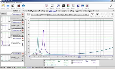
Impedance measurement, this time I didn't do calibration again,just use the data saved in REW system.
View attachment 32276
T/S parameters with 14g Mass T/S parameters with 7g Mass
View attachment 32277
Sd is 123.3 cm2, cause the center of the cone is not movable,so its area is not contained in Sd.
T/S from vendor, they are still different, is there something wrong in my measurement?
View attachment 32279
Hi icbcodc,
What an interesting thread!
You wonder if your results are right. They are because you have to know that you can only compare what is comparable. We never get the same results as the manufacturer because the conditions are different.
You measure a loudspeaker (A) in a room (B) and the manufacturer measures a loudspeaker (a') in a room (b'). You use the REW software (D) with a sound card (E) under a temperature (F) and the manufacturer uses the LMS software (d') with a sound card (e') under a T° (f').
The ambient temperature T° changes the speed of sound C and it also has its influence.
C is calculated with the formula C = 331.3 × square root (1 + (T° / 273.15)) .
Your measurements are accurate and your perseverance is remarkable. By following your thread, I can see my own mistakes and questions. It is an instructive thread.
With your two curves, all that remains is to calculate the TS parameters of your loudspeaker with the dual-mass method.
You will inevitably obtain TS data different from those of the manufacturer and it will be normal.
When you measure your second loudspeaker, the data will be different from the first one and this will be normal too. This is due to manufacturing differences.
Well done and keep up the good work.
You can use the measurements you have to run the results for dual added mass. That will also produce a plot of Bl on the Impedance & Phase graph, it should be flat in the region around Fs if the measurements are good. You could add some diagonal struts from the back and front of the base to the region near the driver mount to stiffen the frame.

Can you attach the mdat file with the 3 measurements? Not sure why Bl should be N/A.
Can you attach the mdat file with the 3 measurements? Not sure why Bl should be N/A.


On your question about masses, using smaller masses is OK, but not too small, for dual added mass I would advise not less than 25% of Mms for mass 1 and not less than 50% for mass 2. There has been a lot of research on more accurate motional and impedance models for drivers since that book was published, and more accurate methods for fitting those models to the driver impedance measurements. Some relevant papers are listed in the REW help. The dual added mass method is one of the results of that research. The model fitting methods used in REW and other modern software do not require such large changes in the resonant frequency.

That is the principle, but the input impedance of the soundcard, the series and shunt impedance of the test leads and the frequency-dependent gain difference between the channels must also be included so the actual calculation is more complicated.BTW, I draw a circuit and a formula, is this the basic way you calculate the Impedance in REW?
That is the principle, but the input impedance of the soundcard, the series and shunt impedance of the test leads and the frequency-dependent gain difference between the channels must also be included so the actual calculation is more complicated.
Thank you, John. It's good to know that.I discussed that comment with Claus and did testing with all REW's sweep lengths and found no difference for sweeps above 5 seconds (256k at 48 kHz sample rate, for example). The noise filter was more important for obtaining reliable results, since sweeps are more susceptible to the effects of external noise. REW already shows a warning if the selected sweep is too short.
Thanks. I have fixed the Bl display for the next beta release, however there is a problem with the measurements. The motional model fit is very different between them, I think the most likely reason is that the measurements of the added masses are not accurate. Even small errors in the mass figures make a large difference to the results, a precision scale is needed and when removing the masses from the cone it should be moved as little as possible.