Speaker Impedance measurement ,circuit and sound card output

icbcodc

New Member
Thread Starter
Joined
Apr 29, 2020
Messages
187
Hello,I'm new guy and sorry for my poor English first.

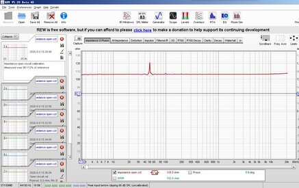
Something wrong and I can't get the Impedance curve when I'm trying to measure the impedance curve of my speakers(for cars) refering the help files of REW 5.19.

My sound car is Behringer UMC22 with input and ouput sockets like this:
31287


I've confirmed with the seller that the OUTPUTS is line out,and the input(MIC/LINE 1) is line in. I use OUTPUTS 2(R) as the output and MIC/LINE 1 as input

31288


My circuit is like this:
31289


Actual connection is like this:
31290


First part ends here for saving purpose.
 
Last edited:

icbcodc

New Member
Thread Starter
Joined
Apr 29, 2020
Messages
187
I've checked the line I made many times,I'm sure the connection is correct.

I make a calibration for the Impedance Rig

I just short out the Rsense following the instruction in REW help, and check the new connection is correct like this:

31291


Actual circuit is like this below, I 've checked the connection is correct.
31292


output/input volume adjusted:
31293


CHECK LEVEL IN REW:
31294


AFTER CALIBRATION,is the result 100Ohm correct?

31295


What does this mean : "100.00% of reference" ?

31296
 
Last edited:

icbcodc

New Member
Thread Starter
Joined
Apr 29, 2020
Messages
187
31297


Short the test leads which should be connected to the pole of speaker later. Is this connection right?

31298


The level for zero ohm calibration is too high,I don't know why.
31299


I just turn down the main ouput level (to 8 clock) of sound card shown below.

31300


check level again ,it seems O.K

31301


There's nothing,is it right? Does this mean test leads resistance is zero?

31302


nothing available.

31303


Is there anything wrong?
 

icbcodc

New Member
Thread Starter
Joined
Apr 29, 2020
Messages
187
Finally, I connect the leads to my speaker,and run the impedance measurement,there is nothing, the sound of sweep from speaker is very low.

31304


31305


What did I do incorrectly? Why I could not get the impedance curve?
 

John Mulcahy

REW Author
Joined
Apr 3, 2017
Messages
7,213
Mic/Line 1 is a single, balanced input, not a stereo input. Inst 2 is the second input channel.
 

icbcodc

New Member
Thread Starter
Joined
Apr 29, 2020
Messages
187
Mic/Line 1 is a single, balanced input, not a stereo input. Inst 2 is the second input channel.

Thank you so much John, It seems you are right.

In the UMC22 manual, "Inst 2" is "1 x ¼" TRS (Instrument)" .

I found TRS stands for Tip(signal)、Ring(signal)、Sleeve(ground), so this is the stereo input, am I right?

In the manual, "MIC/LINE 1" is “XLR/TRS combo connector”,but this TRS is no stereo?

31306


Maybe I should try it tomorrow.
 

John Mulcahy

REW Author
Joined
Apr 3, 2017
Messages
7,213
I would say neither is stereo, they are both mono balanced inputs. Tip and ring are the + and - of the balanced connection.
 

icbcodc

New Member
Thread Starter
Joined
Apr 29, 2020
Messages
187
I would say neither is stereo, they are both mono balanced inputs. Tip and ring are the + and - of the balanced connection.

My goodness,so I use the wrong soudcard.

I will buy a second hand USB soundcard (ASUS XONAR U3 PLUS) today.

31329


31330


Is this the right soundcard for measurement?
 

icbcodc

New Member
Thread Starter
Joined
Apr 29, 2020
Messages
187
It is probably OK.

Hi John, I have a few question about the impedance measurement in latest REW version.

In the "Make a measurement" window, "Open circuit cal" means the following circuit?

31376


"Short Circuit Cal" means the following circuit?

31377


"Reference Cal" means the following circuit?

31378


If my understanding is right, the value of the reference resistor should be 100ohn or lower?

Should I use a 10ohm resistor, when the uppper Rsense in the rig is 100ohm?
 

John Mulcahy

REW Author
Joined
Apr 3, 2017
Messages
7,213
Yes, those are correct. The cabling up to the load connection should be left in place. The reference measurement resistor should be of the same order as the loads being measured, so for speaker measurements probably 50 ohm or lower.
 

icbcodc

New Member
Thread Starter
Joined
Apr 29, 2020
Messages
187
Yes, those are correct. The cabling up to the load connection should be left in place. The reference measurement resistor should be of the same order as the loads being measured, so for speaker measurements probably 50 ohm or lower.

About reference resistor

My speaker (the load you mean) which will be measured is about 4 ohm,so in "3.reference cal",the reference resistor should be around 50ohm or lower?

About RSENSE resistor
My speaker which will be measured is about 4 ohm, but in REW help file, 100ohm Rsense resistor is recommanded, so I've bought a 100ohm Rsense resistor which is still not delivered.

31421


But in the famous book of Joseph D'Appolito 《TESTING LOUDSPEAKERS》 1998, he used a 1000 ohm resistor. Is 1000 ohm RSENESE resistor still fine in the REW measuring circuit ? Because the 100 ohm RSENSE resistor is still not delivered,I have only a 1000 ohm resistor now.

Sorry,the version of my book is not English.

31422


He manually calculated the value with many equations.

31423


Second hand Asus Xonar U3 PLUS is received.

31424
 
Last edited:

John Mulcahy

REW Author
Joined
Apr 3, 2017
Messages
7,213
A higher sense resistor will increase noise levels, I don't recommend that. 50 ohm is fine for the reference resistor.
 

icbcodc

New Member
Thread Starter
Joined
Apr 29, 2020
Messages
187
A higher sense resistor will increase noise levels, I don't recommend that. 50 ohm is fine for the reference resistor.

Thanks John.

I will buy a 50 ohm resistor to use.

And I made a test today,the U3 PLUS sound card was not passed "open circuit" calibration.

31426


and in the check level window, the level of left and right channels are different.

31427


I checked the circuit using a multimeter, it's right. So I have to get U3 PLUS refunded,and buy another USB soundcard.
 

Attachments

  • U3 PLUS TEST UNPASS.jpg
    U3 PLUS TEST UNPASS.jpg
    177.1 KB · Views: 16

John Mulcahy

REW Author
Joined
Apr 3, 2017
Messages
7,213
And I made a test today,the U3 PLUS sound card was not passed "open circuit" calibration.
I'm not sure what you mean by "not passed", calibration is not a pass/fail. There is some noise at 50 Hz which looks like mains pickup but otherwise it looks OK. The difference between the channels isn't large enough to cause a problem, calibration compensates for it.
 

icbcodc

New Member
Thread Starter
Joined
Apr 29, 2020
Messages
187
I'm not sure what you mean by "not passed", calibration is not a pass/fail. There is some noise at 50 Hz which looks like mains pickup but otherwise it looks OK. The difference between the channels isn't large enough to cause a problem, calibration compensates for it.

Oh,but why the software tells me the Calibration is not valid,I think it means "not passed".

31428
 

John Mulcahy

REW Author
Joined
Apr 3, 2017
Messages
7,213
Ah, I was looking at the wrong figure in your previous images. That is a larger difference than should be expected between the channels of a soundcard.
 

icbcodc

New Member
Thread Starter
Joined
Apr 29, 2020
Messages
187
Ah, I was looking at the wrong figure in your previous images. That is a larger difference than should be expected between the channels of a soundcard.

Yes,I've taken this soundcard back to seller.
 

icbcodc

New Member
Thread Starter
Joined
Apr 29, 2020
Messages
187
Ah, I was looking at the wrong figure in your previous images. That is a larger difference than should be expected between the channels of a soundcard.

Hi John

Unfortunatly,the test result is still bad with another soundcar (SB0271,soundblaster).

I've made sure that the left and right channel level in the software are same.

Should I adjust the balance of left and right channel to make the test result good or buy another soundcard?

31478
 

jtalden

Senior Member
Joined
May 22, 2017
Messages
887
Location
Arizona, USA
More  
Preamp, Processor or Receiver
Marantz AV7705 Pre/Pro
Main Amp
VTV 6 chnl NC252MP P-amp x 2
Additional Amp
Behringer DCX2496 x 2
Universal / Blu-ray / CD Player
OPPO BDP-103 Universal Player
Front Speakers
DIY SEAS H1456/H1212 Spkr x 5
Subwoofers
DIY JBL 2235H 15" SW x 2
Video Display Device
JVC DLA-X790R
Screen
Da-Lite Da-Snap 39105V - 92"
I noticed in Post-15 REW 'Soundcard Preferences' picture that:
Measurement Channel; output = R, input = L
Reference Channel; output = L, input = R
I don't know if this cross channel setup could cause the channel balancing problem or not, but you may want to try changing it to the more conventional setup.
 

icbcodc

New Member
Thread Starter
Joined
Apr 29, 2020
Messages
187
I noticed in Post-15 REW 'Soundcard Preferences' picture that:
Measurement Channel; output = R, input = L
Reference Channel; output = L, input = R
I don't know if this cross channel setup could cause the channel balancing problem or not, but you may want to try changing it to the more conventional setup.

I don't know how to do the conventional setup,sometimes I am also confused by the bad result. I just read the help file for impedance measurement and ask somebody who did that before and watch some Youtube videos.
 
Top Bottom