Sound Card Calibration and Impedance Circuit

sm52

Member
Thread Starter
Joined
Mar 14, 2019
Messages
863
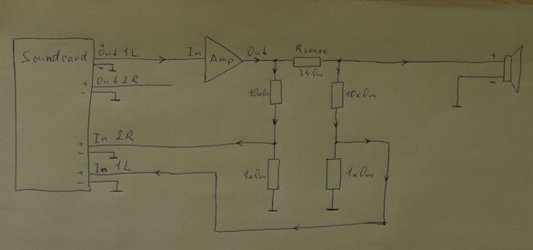
On the old version of REW, I was able to calibrate the sound card and measure the impedance of the speakers. On the latest version, I can’t calibrate. I use an amplifier and a voltage divider to protect the sound card inputs. Questions.
1. If an amplifier and voltage divider are used, is it necessary to calibrate the sound card separately? It always works with an amplifier. Maybe you need to calibrate the sound card with the amplifier. How?

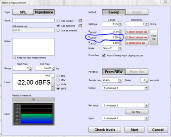
At the 2nd calibration step
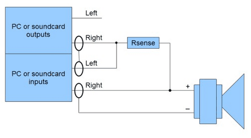
2. If use only a sound card for calibration, it's need to short-circuit the + and - inputs of the sound card. It is safe?
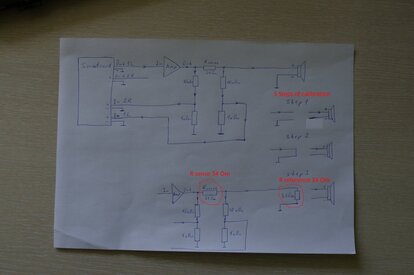
3. If use a sound card with an amplifier for calibration, it is necessary to short circuit the + and - outputs of the amplifier. Because the Rsense resistor in the 1st and 2nd step must be shorted. It is safe?
 

Attachments

  • impedance measurement circuit.jpg
    impedance measurement circuit.jpg
    66.2 KB · Views: 346
  • impedance measurement circuit.PNG
    impedance measurement circuit.PNG
    14.7 KB · Views: 317
Last edited:

Vladimir_1953

New Member
Joined
Jul 5, 2018
Messages
39
More  
Preamp, Processor or Receiver
ROTEL RC-990
Main Amp
ROTEL RB-991
Universal / Blu-ray / CD Player
DENON DCD-2000AE, ROTEL RCD-991AE
Front Height Speakers
Dynaudio Crafft
Only the reference resistor is shorted, and not the output of the sound card.
For an amplifier and sound card it is safe.
 

John Mulcahy

REW Author
Joined
Apr 3, 2017
Messages
7,212
The calibration process for the current beta version uses open circuit, short circuit and reference resistor calibration steps, the sense resistor is always in circuit. Any setup you use should be capable of driving a short circuit load, looks like you have a 34R sense resistor so that shouldn't be a problem for your amplifier if it is capable of driving a speaker directly.
 

sm52

Member
Thread Starter
Joined
Mar 14, 2019
Messages
863
This means that the resistor is always in the circuit and it does not need to be shorted. When I do the 1st calibration step, should the value of the resistor be entered in its field or should it be 0?
 

John Mulcahy

REW Author
Joined
Apr 3, 2017
Messages
7,212
Leave it at its actual value, just follow the new instructions linked above. Most important in the new process is the accuracy of the value of the reference resistor used in the last step of the calibration.
 

sm52

Member
Thread Starter
Joined
Mar 14, 2019
Messages
863
If an amplifier and voltage divider are used, is it necessary to calibrate the sound card separately? It always works with an amplifier. Maybe is needed to calibrate the sound card with the amplifier?
 

sm52

Member
Thread Starter
Joined
Mar 14, 2019
Messages
863
Then I can forget to say, this does not apply to the topic. The download page has strange dates. That is it should be?
 

Attachments

  • Date.PNG
    Date.PNG
    161.8 KB · Views: 50

John Mulcahy

REW Author
Joined
Apr 3, 2017
Messages
7,212
The only calibration needed is the calibration in the instructions. The dates you highlighted are when the threads for those OS versions started, each new build is an update on the original thread.
 

sm52

Member
Thread Starter
Joined
Mar 14, 2019
Messages
863
I did the calibration according to the instructions. Here's what happened. It seems to me that something is wrong.
At the 3rd calibration step, it is said to turn on the reference resistor instead of the load and enter the exact value in the input field. On my circuit, the Rsense reference resistor. You wrote that it should always be connected. Do I need to connect another reference resistor instead of a speaker?
 

Attachments

  • Calibrating.PNG
    Calibrating.PNG
    136.1 KB · Views: 40

sm52

Member
Thread Starter
Joined
Mar 14, 2019
Messages
863
On the right in the figure, I drew 3 calibration steps. Is everything right?
 

Attachments

  • IMGP2222.JPG
    IMGP2222.JPG
    141.3 KB · Views: 244

John Mulcahy

REW Author
Joined
Apr 3, 2017
Messages
7,212
Yes. The reference resistor doesn't need to be the same value as your sense resistor, for best accuracy it should be similar to the impedance of the speaker you are measuring but it is not too critical as long as it is not a lot higher than the speaker impedance. 34 ohm should be fine.
 

sm52

Member
Thread Starter
Joined
Mar 14, 2019
Messages
863
The sound card itself has an input impedance of 2800 ohms. But after the amplifier there is a 10 kOhm resistor. What is the value to record for the input impedance of the sound card? 2800 Ohm or 12800 Ohm?
 

Attachments

  • Input impedance of the soundcard.PNG
    Input impedance of the soundcard.PNG
    27.4 KB · Views: 105

John Mulcahy

REW Author
Joined
Apr 3, 2017
Messages
7,212
The effective impedance for that setup is 10736 ohm, 10k in series with the parallel combination of the 1k and 2.8k, but it isn't too critical since the calibration steps will produce the correct result even if that figure is wrong.
 

sm52

Member
Thread Starter
Joined
Mar 14, 2019
Messages
863
These are sound card calibration graphs at -22db, -18db, -12db levels. After 1 kHz there is a difference. At what levels of the test signal, volume level and gain level on the sound card should the most correct graph be obtained?
 

Attachments

  • Soundcard calibration -12db.PNG
    Soundcard calibration -12db.PNG
    110.2 KB · Views: 101
  • Soundcard calibration -18db.PNG
    Soundcard calibration -18db.PNG
    110.4 KB · Views: 100
  • Soundcard calibration -22db.PNG
    Soundcard calibration -22db.PNG
    107.1 KB · Views: 87

Bernard

Member
Joined
May 22, 2017
Messages
120
Hello,
If you are reckless, you will try a sweep level of 0 dBu ( -2.2 dBFS) to get the best signal-to-noise ratio with a headroom of -1 dB only. This is not a joke. The overload lights on the soundcard will blink and be red but it will pass!
If you're not very sure, you try a step-by-step lowering of 1 dBFS until the sound card no longer accepts torture and displays a garbled line.
I don't think John will contradict me.
I didn't dare to do it, but I did. It works when the sound card is good. And to check the distortion, it's best to use the RTA function.
 

John Mulcahy

REW Author
Joined
Apr 3, 2017
Messages
7,212
These are sound card calibration graphs at -22db, -18db, -12db levels. After 1 kHz there is a difference.
I don't see any difference in the graph shapes, just slightly higher noise at the higher levels.
 

sm52

Member
Thread Starter
Joined
Mar 14, 2019
Messages
863
John, thanks for the answers. I managed to measure the impedance of all the speakers.
 

Attachments

  • impedance of 4 speakers.PNG
    impedance of 4 speakers.PNG
    336.2 KB · Views: 67

sm52

Member
Thread Starter
Joined
Mar 14, 2019
Messages
863
I am taking IR measurements using the ARTA program. But I would like to learn how to do it with REW. Is there a thread on this forum? Maybe there is a video?
 

John Mulcahy

REW Author
Joined
Apr 3, 2017
Messages
7,212
It isn't much different to taking an impedance measurement, just select the input and output you are using for your mic and speakers. The help for it is here and there are some guides here.
 

sm52

Member
Thread Starter
Joined
Mar 14, 2019
Messages
863
John, if I calibrated the sound card at -12 dB, should I do all measurements at the same level? May I discuss here impedance measurements for calculating Tielle-Small parameters?
 

John Mulcahy

REW Author
Joined
Apr 3, 2017
Messages
7,212
Level shouldn't matter much for the calibration. When measuring driver impedance make sure the terminal voltage across the driver isn't too high, 100 mV or less.
 

sm52

Member
Thread Starter
Joined
Mar 14, 2019
Messages
863
I figured out the calibration. My question is about further measurements after calibration. About measuring speaker impedance. I made 3 impedance measurements at -12, -6, -3 dB. The resonance frequency changed from 55 Hz to 52 Hz. Minus 1.5 Hz on each measurement. Therefore, it is not clear at what level the speaker impedance should be measured in order to obtain the most accurate results. Calibration before measuring impedance was done at -12 dB. A circuit without an amplifier.
 

John Mulcahy

REW Author
Joined
Apr 3, 2017
Messages
7,212
The change in FS as you alter the measurement level is not related to the calibration.
 

sm52

Member
Thread Starter
Joined
Mar 14, 2019
Messages
863
May I discuss here impedance measurements for calculating Tielle-Small parameters?
 
Top Bottom