To align the impulses, you should look at the peak of the impulse after the first rise of the graph from the zero level. Therefore, the highlight should start at one peak at the top of the zero level and end at the second peak at the top of the zero level.regardless if it points up or down
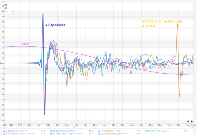
If you have multiple acoustically synchronized measurements, you can figure out the offset time for any graph relative to any. If you want the distance (time of arrival of the signal) from the left speaker to the microphone to be equal to the distance (time of arrival of the signal) from the right speaker to the microphone, select the area from the positive peak of the impulse of the left speaker to the positive peak of the impulse of the right speaker. In the same way, act to align a sub with the left speakers. And a sub with the right speaker. It may turn out that the time (distance) to which you need to shift the left speaker for coordination with the subwoofer is not equal to the time (distance) to which you need to shift the right speaker for coordination with the sub.
Last edited: