


Hello John,
How is it going?
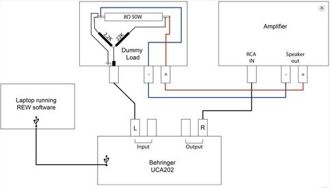
I'm preparing to measure the Frequency Response and Distortion of my amplifiers (4x150w RMS and 4x80W RMS, these amplifiers are car audio products, and the impedance of the speaker is 4 Ohm). To prevent from destroying my sound card,I made some research (here)(this article was not written by me, I just use it for reference), and I will prepare to make a circuit like this below.
And My sound card is Beringer UMC202HD, which supports 24bit 192KHz.
Should I choose 1/4W version for the resistors (2.2K Ohm and 22K Ohm)? Does it matter?
Actu

Updated 2021.12.18
This circuit is the simplest one, and it comes from this article "Howto - Distortion Measurements with REW"
There is no votage divider in this simplest circuit.

There is a fix divider in the circuit to protect the soundcard.

UMC202HD Specifications: Line Max. input level +20dBu Mic in Impedance 3000Ohm

How is it going?
I'm preparing to measure the Frequency Response and Distortion of my amplifiers (4x150w RMS and 4x80W RMS, these amplifiers are car audio products, and the impedance of the speaker is 4 Ohm). To prevent from destroying my sound card,I made some research (here)(this article was not written by me, I just use it for reference), and I will prepare to make a circuit like this below.
And My sound card is Beringer UMC202HD, which supports 24bit 192KHz.
Should I choose 1/4W version for the resistors (2.2K Ohm and 22K Ohm)? Does it matter?
Actu
Updated 2021.12.18
This circuit is the simplest one, and it comes from this article "Howto - Distortion Measurements with REW"
There is no votage divider in this simplest circuit.
There is a fix divider in the circuit to protect the soundcard.
UMC202HD Specifications: Line Max. input level +20dBu Mic in Impedance 3000Ohm
Attachments
Last edited:

")
 But I will try to get some useful information from it.


