Really cool !! I agree wholeheartedly about the utility of the RPi. It is such an amazing tool !!! I am making amplifiers and recording equipment which is more for character than 100% linearity. So finding tools that help me 'characterize' the interesting contraptions I make are extremely helpful. Your posts are like gold !! I mention that to encourage your efforts and sharing.. Also to let it be known that even though people may not vocally appreciate all the time >> you are appreciated. your efforts are important and cool. Blazing new trails is not exactly 'trivial'


-
AUDIO VIDEO PROCESSING, SETUP & ENVIRONMENTOfficial REW (Room EQ Wizard) Support Forum Audiolense User Forum Calibration Equipment Auto-EQ Platforms / Immersive Audio Codecs Video Display Technologies / Calibration AV System Setup and Support Listening Room / Home Theater Build Projects Room Acoustics and Treatments AV Showcase Movies / Music / TV / Streaming
-
AUDIO VIDEO DISCUSSION / EQUIPMENTHome Theater / Audio and Video - Misc Topics Essence For Hi Res Audio AV Equipment Advice and Pricing Awesome Deals and Budget AV Equipment AV Receivers / Processors / Amps UHD / Blu-ray / CD Players / Streaming Devices Two Channel Hi-Fi Equipment DIY Audio Projects Computer Systems - HTPC / Gaming HD and UHD Flat Screen Displays Projectors and Projection Screens AV Accessories Buy - Sell - Trade
Navigation
Install the app
How to install the app on iOS
Follow along with the video below to see how to install our site as a web app on your home screen.
Note: This feature may not be available in some browsers.
More options
You are using an out of date browser. It may not display this or other websites correctly.
You should upgrade or use an alternative browser.
You should upgrade or use an alternative browser.
Make a good measurement system with REW and Raspberry
- Thread starter Antonio Di Motta
- Start date

Antonio Di Motta
Member
Thank you very much for the encouragement, I have been working on the 4.0 version of the tool for more than a year, which should have professional features. I am currently involved in the design of a sound card dedicated to the raspberry Pi 4.0 with characteristics of low distortion and high linearity and sampling frequency of 192 Khz. I hope to be able to present it in the first few months of 2020 my performance terget is to overcome the Clio audiomatics card, if I succeed I will be very satisfied ..
Thanks again
Antonio Di Motta
Thanks again
Antonio Di Motta
Hi Antonio:
Just to let you know, you are not alone. For quite a while I have been using the Raspberry Pi Zero with a couple of the AudioInjector boards. I had sponsored (kickstarter) the AudioInjector stereo card at 96khz and the AudioInjector Ultra 2 card at 192khz. I wanted no less than 192khz and 24 bits.
Problem with the Ultra 2 card is that it is not set up as a sound card with line in and line out levels. I created test files at max loudness with Audacity and measured something like 32 v peak to peak from the outputs with my oscilloscope. Like you I then started to search for other sound cards for the RPI Zero and wound up with the Hifiberry DAC+ADC Pro.
The Hifiberry unit glitched when I first tried a REW sound card calibration. A very quick response from Daniel at Hifiberry suggested the glitch was fixed but not yet in the download version of Raspbian (Raspberry Pi version of Debian). He suggested I do a:
rpi-update
to update the kernel. The results was a very flat REW sound card calibration.
The Raspberry Pi Zero has plenty of power for the 192khz 24 bit boards when run as a set of alsa commands in terminal mode (aplay and arecord). When playing in Audacity from the desktop, it runs close to 100% on the cpu gage of the desktop while the terminal command of aplay of the same file maxes out at about 14% .
I still need to use REW to set up my 12+12 band Equalizer to equalize my listening room but it hasn't been fruitful so far.
Another add on to the use of the zero and sound card is to capture vinyl at 192khz 24 bit when I receive the boards based on audiokarma's forum on a RIAA pre- amp.
I think we would agree that there is a lot of power in an SBC that is smaller than 1.5 by 3 inches.
I appreciate the time and effort you put into this thread.
Wes Brenner
Last edited:
Antonio Di Motta
Member
Hi Wes Brenner,
I did a lot of tests with the Audioinjector sound cards (Zero and Stereo) and unfortunately I came to the conclusion that they have instability of the frequency response and they are also very noisy.
As for the Raspberry I use the Pi3 Pi3 + version and most recently Pi4, the REW software requires more processing power than the Pi 0 version.
The Hifiberry DAC + ADC Pro sound card certainly corrected a problem they had on the previous version Hifiberry DAC + ADC which had too high an input capacity that limited the frequency response very much.
I had reported this problem to the technical department, but they ignored me, after a short time they changed the card and the characteristics they declare on the Pro seem good.
Currently I am busy designing a sound card based on the Cirrus Logic CS4272 sound chip and I hope to be able to test it as soon as possible to verify correct operation.
Regards
Antonio
Hi Antonio:
Another similarity of our equipment is the linkwitz mod of the wm61a Panasonic mic capsule 2 wire connection (part C in diagram of message number 33 of this thread). Back in the day there were rumors that these capsules (or the wm60a) were so good at bass response they were used for measuring rumblings in volcanoes. Sadly, Panasonic quit producing these gems that were about $2 apiece. Please keep us up to date on your work on the CS4272.
I haven't come across a problem with REW and the Raspberry pi zero but I may be using a different operating system.
I use the most recent release of Raspbian on the RPi zero which is named Buster. For those non linux users, major upgrades to Debian are toy story character's names and Buster is required for the RPi 4.
Wes Brenner
Last edited:
Antonio Di Motta
Member
Hello
I have been using Rew with Raspberry for at least three years and I started working on my project with the Pi3 version, with the Pi zero version I have never tried considering it too underperforming to use with REW, especially when it has to perform calculations for the Waterfall or for display spectrogram or when it has to calculate and display RT60 Decay.
With version 4 with 4Gb of memory these functions are quite performing, I would be curious to see how a Pi zero works but I think it can be much slower.
Currently, for version 4.0 of the instrument, I am using Raspberry Pi4 with Raspian Buster updated to the latest version with kernel version 4.19.97-v7l + # 1294 SMP Thu Jan 30 13:21:14 GMT 2020.
The previous version of the tool 3.0 (that of the post) I used Raspberry PI3 with OS. version Xubuntu 16.04.
Regards
Antonio
Antonio Di Motta
Member
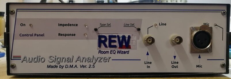
During the downtime for Covid I built a new version of the analyzer which involved the use of a microphone preamplifier with standard + 48V Phanton power supply and one installed the latest beta version of REW the 5.20beta53.
This version of analyzer uses the Beringer ECM8000 microphone and thanks to the continuous updates of REW it has even better performances than the previous one.
Greetings from Italy...
This version of analyzer uses the Beringer ECM8000 microphone and thanks to the continuous updates of REW it has even better performances than the previous one.
Greetings from Italy...
Attachments
Antonio Di Motta
Member
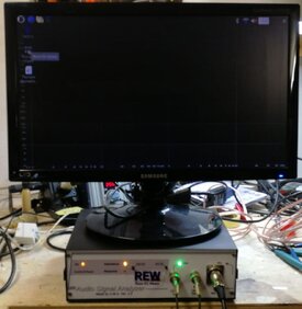
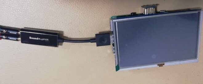
This new version is based on the Raspberry Pi 3+ with zero audioinjector sound card with version of Raspian OS Buster and Oracle java version 8.251 for arm. The sampling frequency is up to 96Khz even if it is not very stable as a frequency response. The best setting is to set the sampling frequency to 88.2Khz and the bandwidth actually usable is between 5Hz to 30Khz.
Antonio Di Motta
Member
Hi Antonio:
Good to see the progress on the sound card. Will it be able to run at 192/24? As we discussed before I have both the audioinjector ultra and the hifiberry adc dac pro but am interested in very low levels of distortion and the 3 ultras have some serious noise at about 200khz. Seems only way to make them usable is to put in a 4th order low pass filter.
It sounds like you are working toward a sound card with good specs. Keep up the good work.
Wes Brenner
... until the new final version!A new, even more performing version will soon be released, which should be the definitive one.
The vaccine against perfectionism has not yet been invented, Antonio. You will always have a little extra touch to add!
")
Antonio Di Motta
Member
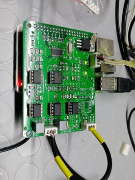
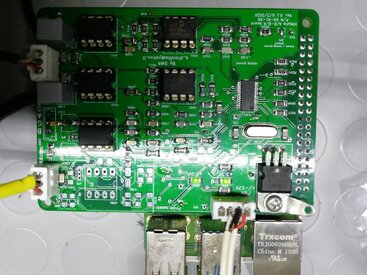
The Vittorio 1 board you have seen is still a test version to evaluate the general functioning and also the goodness of the
drivers for Raspberry OS.
Unfortunately, there is some problem on the drivers in fact in the 64bit version it would seem that the 24bit mode is not available.
Using the 32bit Raspberry OS version the board works at 24bit on all sampling rates.
However this card works with 48Khz- 96Khz and 192Khz sampling frequency, but currently the buffer in and out circuits are
calibrated for 96Khz operation.
Antonio Di Motta
Member
Even though the card is a test version, it definitely performs much better than all the ones I have tested on my audio analyzer and I am quite happy with the result. There is an advanced version in the works which is currently in its third revision and uses completely different buffers to further improve the distortion and noise values. Besides the buffers there are also different voltage regulators which are of the low noise type 20-30uV.
Antonio Di Motta
Member
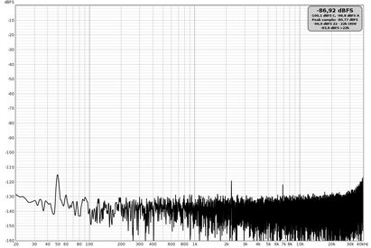
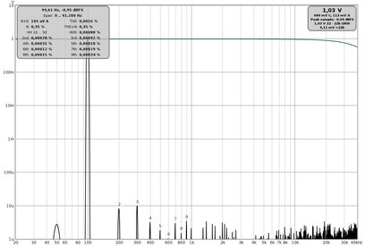
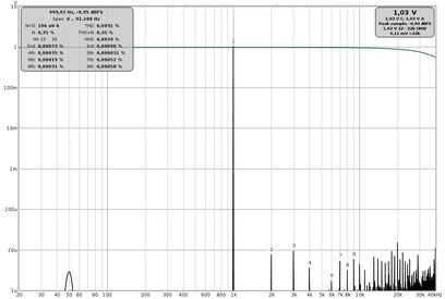
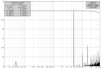
I made some measurements in loop between output and input to make you understand the level of performance reached.
In particular, I am attaching the frequency response, the noise level and the distortion both at 96Khz and 192Khz with the 64bit Raspberry OS operating system and latest beta version of REW 5.20 RC6.
In particular, I am attaching the frequency response, the noise level and the distortion both at 96Khz and 192Khz with the 64bit Raspberry OS operating system and latest beta version of REW 5.20 RC6.
Attachments
-
 96Khz Rumore di fondo.jpg141.6 KB · Views: 125
 -
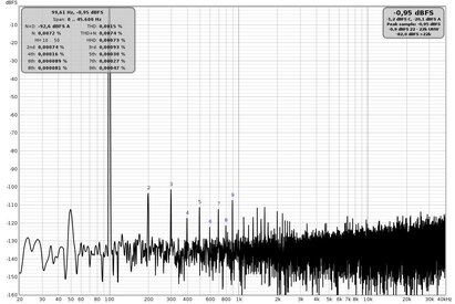 96Khz Distorsione THD 100Hz.jpg158.4 KB · Views: 118
 -
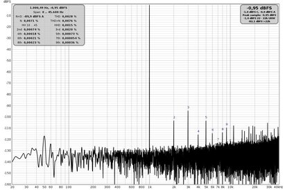 96Khz Distorsione THD 1Khz.jpg156.9 KB · Views: 109
 -
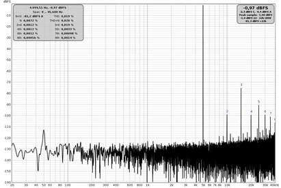 96Khz Distorsione THD 5Khz.jpg155.7 KB · Views: 118
 -
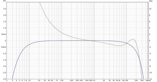 Risposta 96Khz loop.jpg108.7 KB · Views: 120
 -
 Distorsione 96Khz loop.jpg80.8 KB · Views: 118
 -
 192Khz Rumore di fondo.jpg145.8 KB · Views: 107
 -
 192Khz Distorsione THD 100hz.jpg80.8 KB · Views: 103
 -
 192Khz Distorsione THD 1Khz.jpg78.2 KB · Views: 102
 -
 192Khz Distorsione THD 5Khz.jpg76.5 KB · Views: 96
 -
 Risposta 192Khz loop.jpg121.7 KB · Views: 110
 -
 Distorsione 192Khz loop.jpg93.3 KB · Views: 114
Antonio Di Motta
Member
The second example of the card has undergone some minor changes to the input buffer power level as it was affected by a design error that caused the cs4272 audio chip to break when the input signal was very strong. Currently I have not had more problems, the next post I will send some impedance measurements made with this card.
Thanks for the attention.
Thanks for the attention.
Attachments
Antonio Di Motta
Member
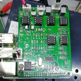
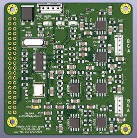
The cs4272 audio chip is very valid and has excellent performance but has the disadvantage of not having the input and output buffer circuits inside, so it must be completely designed and the quality of this project affects the performance of the entire card. . The quality of the components is of fundamental importance, in fact the evolution of the board has been designed to use all SMD components to minimize the overall dimensions and further reduce the background noise. At the moment the card is still in the planning phase but I can already show how it will look.
Unfortunately, the quality of the components involves a significant increase in manufacturing costs, but this is inevitable. It will still take some time to build it, also because I use this test version to experiment with the changes to be implemented, I hope to be able to build it by the end of 2021, after which I will start building version 4 of the audio analyzer based on REW and Rasberry. Thanks for the attention.
Unfortunately, the quality of the components involves a significant increase in manufacturing costs, but this is inevitable. It will still take some time to build it, also because I use this test version to experiment with the changes to be implemented, I hope to be able to build it by the end of 2021, after which I will start building version 4 of the audio analyzer based on REW and Rasberry. Thanks for the attention.
Attachments
Hi Antonio,
I won't talk about Arduino because I am at odds with IT language, I could never write a single line of code except in Basic (and Fortran when I was at school), but I have started researching soundcards, and so far I could find several that had enough faults for being rejected. For a start, none of the built-in soundcards in my desktops had any half-decent noise level, so I chose to research only USB cards.
The 1st one, an Icon, was perfect in terms of integration: only line levels, no switches, no pots, but it turned out the fequency response had about 4-4 db ripple in the passband!
The 2nd one was a Behringer UMC202HD, which I never could make to work satisfactorily at 192kHz.
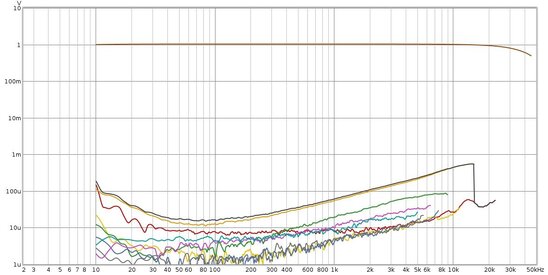
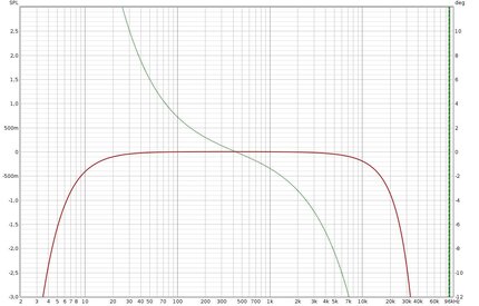
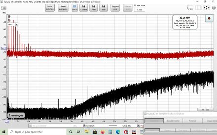
I finally opted for a Native Instruments Komplete Audio 2, that seemed to be flawless, until I figured out the noise shaping used to improve the perceived Signal/Noise ratio actually shifted the noise density towards high frequencies and that no analog filtering happened after.The actual S/N ratio above 20kHz is about 40dB. It resulted in compressors seeing parasitic signals that fooled the detectors and created wrong compression curves.
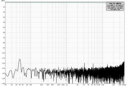
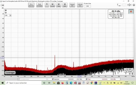
The second graph shows how low-pass filtering at 22kHz retrieves the claimed S/N ratio, but I want to be able to measure up to about 90kHz.
I decided to make a brickwall filter (8th-order Chebishev at 92kHz)); I'm expecting PCB's soon.
I won't talk about Arduino because I am at odds with IT language, I could never write a single line of code except in Basic (and Fortran when I was at school), but I have started researching soundcards, and so far I could find several that had enough faults for being rejected. For a start, none of the built-in soundcards in my desktops had any half-decent noise level, so I chose to research only USB cards.
The 1st one, an Icon, was perfect in terms of integration: only line levels, no switches, no pots, but it turned out the fequency response had about 4-4 db ripple in the passband!
The 2nd one was a Behringer UMC202HD, which I never could make to work satisfactorily at 192kHz.
I finally opted for a Native Instruments Komplete Audio 2, that seemed to be flawless, until I figured out the noise shaping used to improve the perceived Signal/Noise ratio actually shifted the noise density towards high frequencies and that no analog filtering happened after.The actual S/N ratio above 20kHz is about 40dB. It resulted in compressors seeing parasitic signals that fooled the detectors and created wrong compression curves.
The second graph shows how low-pass filtering at 22kHz retrieves the claimed S/N ratio, but I want to be able to measure up to about 90kHz.
I decided to make a brickwall filter (8th-order Chebishev at 92kHz)); I'm expecting PCB's soon.
Attachments
Antonio Di Motta
Member
Hello JLM1948, your latest sound card actually increases the noise above 30Khz and actually seems to be poorly filtered on the DAC output, but the input stage should also be checked to understand where the problem actually is. Have you tried and loop between input and output to check the overall in / out response? From the overall frequency response it is possible to verify what type of cut has been used on the input buffers, even if it is difficult to understand if the cut is dependent on the input section or on the output section. In order to understand you should use a second sound card with known characteristics and loop this card for example using it as an input and test the use of the last card using it as an output.
Antonio Di Motta
Member
My sound card, I use it up to 40Khz even though the sampling rate is 192Khz.
Beyond the frequency of 40Khz the THD increases considerably and depending on the type of measurement this could be a problem.
Beyond the frequency of 40Khz the THD increases considerably and depending on the type of measurement this could be a problem.
Antonio Di Motta
Member
The sound card that I am still making is intended exclusively for use with Raspberry Pi in version 3.0 and 4.0 and is currently still in the prototype phase and subjected to instrumental tests to verify correct operation. I don't hide from you that calibrating the cut in frequency of the input and output buffers is giving me a lot of problems, and currently the card only has a second order filter (12db / oct) at the output but none at the input. Since I will use this card exclusively to carry out measurements with REW, I will try to optimize the performances in terms of S / N and THD and of course the linearity of frequency response, this is necessary for me to make precise response measurements in the environment with the use of the measurement microphone but also of amplification or response systems of cross-over filters. Another measurement that I intend to carry out with the utmost precision is that of the electrical impedance of electroacoustic systems. When I have set up the card, the impedance and response measurements in the environment and all the others I have mentioned will be inserted.
Have fun making the 8th-order Chebishev filter at 92kHz, even if I would not use the maximum band and I would stop at 70Khz which I think is more than adequate for electroacoustic purposes.
Greetings Antonio
Have fun making the 8th-order Chebishev filter at 92kHz, even if I would not use the maximum band and I would stop at 70Khz which I think is more than adequate for electroacoustic purposes.
Greetings Antonio
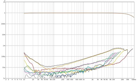
this test is actually some kind of loopback. I just inserted an interface I have designed that adds very little noise to the system, and only white noise. The global frequency response is straight to 92kHz. The noise FFT with the input disconnected is about 30dB less, so there is no doubt that noise is generated by the DAC. I spoke with the manufacturer's technical service and they acknowledged the issue, which is not a problem for them, since they address specifically the music market, and never claimed to make instrumentation grade equipment.Hello JLM1948, your latest sound card actually increases the noise above 30Khz and actually seems to be poorly filtered on the DAC output, but the input stage should also be checked to understand where the problem actually is. Have you tried and loop between input and output to check the overall in / out response? From the overall frequency response it is possible to verify what type of cut has been used on the input buffers, even if it is difficult to understand if the cut is dependent on the input section or on the output section. In order to understand you should use a second sound card with known characteristics and loop this card for example using it as an input and test the use of the last card using it as an output.
I agree with you that 70kHz is certainly enough for most acoustic measurements (at least for equipment designed for humans), but for electronics, I've been spoiled using the Audio Trecision system that goes up to 200kHz and beyond.
Antonio Di Motta
Member
It is absolutely difficult if not impossible to equal the performance of the Audio Precision measurement system, I myself who have a digital oscilloscope for analog use Picoscope 4262 with spectral analysis software up to 5Mhz I cannot get close to the performance of an Audio Precision. All sound cards, however good, will not be able to compete with a professional measurement system, you just have to use it in the best possible way compatible with your needs.
For this I have undertaken the construction of the sound card in order to better adapt it to my technical needs.
As for your sound card, it seems unlikely to me that you can equalize the average noise level up to 92Khz without significantly varying the output response to the DAC. The noise is however also a component of the signal and often cannot be eliminated with a simple filter at the output of the system but must be eliminated at the root, that is, eliminating those components or that particular circuit configuration that produces them. Often when USB sound cards are used the power supply circuits are the major source of noise as they use high frequency oscillators to raise the voltage of the 5V typical of the USB interface, this produces an electrical noise that if not well filtered increases the noise level. of the whole board and this happens above all at very high frequencies.
I didn't want to demoralize you, but keep experimenting and update us on your progress.
Greetings Antonio
I'm very much aware of that. However, I can do 90% of the measurements I need with that set-up. Once I have solved the noise issue, I can do 99%.It is absolutely difficult if not impossible to equal the performance of the Audio Precision measurement system, I myself who have a digital oscilloscope for analog use Picoscope 4262 with spectral analysis software up to 5Mhz I cannot get close to the performance of an Audio Precision. All sound cards, however good, will not be able to compete with a professional measurement system, you just have to use it in the best possible way compatible with your needs
With the 8th-order filter, I can equalize the response up to 90kHz with minimum impact on the passband response. Chebyshev with 0.1dB ripple is fine by me.As for your sound card, it seems unlikely to me that you can equalize the average noise level up to 92Khz without significantly varying the output response to the DAC.
This is not at all the case. The level of extraneous spurii due to interference is negligible compared to the noise-shaped quantization noise.The noise is however also a component of the signal and often cannot be eliminated with a simple filter at the output of the system but must be eliminated at the root, that is, eliminating those components or that particular circuit configuration that produces them. Often when USB sound cards are used the power supply circuits are the major source of noise as they use high frequency oscillators to raise the voltage of the 5V typical of the USB interface, this produces an electrical noise that if not well filtered increases the noise level. of the whole board and this happens above all at very high frequencies
You won't demoralize me. I have already ordered the PCB for the filter, expect to receive it next thursday.I didn't want to demoralize you, but keep experimenting and update us on your progress.
goginux
Member
- Joined
- Sep 15, 2020
- Posts
- 35
More
- Preamp, Processor or Receiver
- denon 3801
- Main Amp
- arcam alpha 2
- Additional Amp
- philips fa860
- Other Amp
- denon 910
- Universal / Blu-ray / CD Player
- onkyo
- Streaming Equipment
- android box
- Streaming Subscriptions
- dac usb
- Front Speakers
- diy
- Center Channel Speaker
- dynaudio
- Surround Speakers
- dali
- Surround Back Speakers
- dynaudio back
- Front Height Speakers
- philips
- Rear Height Speakers
- dali
- Subwoofers
- dali bose
- Other Speakers
- denon sansui
- Screen
- lg
- Video Display Device
- samsung
- Remote Control
- one for all
- Satellite System
- diy spaekers
- Other Equipment
- pioneer sacd


Popular tags
20th century fox
4k blu-ray
4k uhd
4k ultrahd
action
adventure
animated
animation
bass
blu-ray
calibration
comedy
comics
denon
dirac
dirac live
disney
dolby atmos
drama
fantasy
hdmi 2.1
home theater
horror
kaleidescape
klipsch
lionsgate
marantz
movies
onkyo
paramount
pioneer
rew
romance
sci-fi
scream factory
shout factory
sony
stormaudio
subwoofer
svs
terror
thriller
uhd
ultrahd
ultrahd 4k
universal
value electronics
warner
warner brothers
well go usa