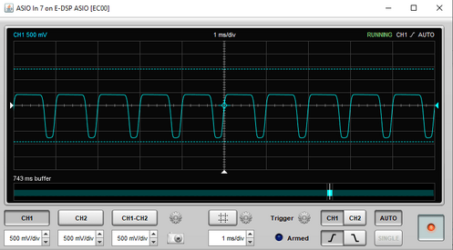
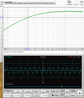
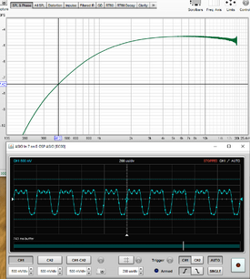
My apologies, I'm relatively new to your software and was going off a YouTube where they explained how they used your software to measure a device patched in loopback. They used your soundcard calibration feature, which seems ideal with is wizard workflow and the fact the only need is for a sine sweep frequency response plot. The issue I encountered can be reproduced by doing Preferences>Soundcard>Calibrate soundcard>Next>Next>Next>Next and then on SPL & Phase tab select dBFS for left axis for the plot (of course after patching in a device to test). But if there is a better way to do this, I'll try it out. All of that said, the graph generated by the above workflow appears fine except that the frequency values are low by a factor of 10 compared to analog oscilloscope and RMAA. I would think its still an issue even using this feature only for its intended purpose of creating a soundcard compensation profile.
I read the help file for the loopback timing reference feature you mentioned and what I'm getting out of that is it seems to be for aligning an IR that can be generated. Again, my apologies for stumbling thru this since I'm pretty new to your product. If that is what its for, I don't need an IR of the response (though that does give me some cool ideas), all I need is a sine sweep plot to validate a piece of hardware. (for anyone following this thread and guessing the 1st order high pass with 2.6KHz cutoff is a Dallas Rangemaster, you'd be right :-))
Thanks for your help and let me know if I can provide anything to assist. You mention mdat file, I'll go read the help and see if I can come up with it for you if its still needed after my hopefully more understandable explanation.


")