


-
AUDIO VIDEO PROCESSING, SETUP & ENVIRONMENTOfficial REW (Room EQ Wizard) Support Forum Audiolense User Forum Calibration Equipment Auto-EQ Platforms / Immersive Audio Codecs Video Display Technologies / Calibration AV System Setup and Support Listening Room / Home Theater Build Projects Room Acoustics and Treatments AV Showcase Movies / Music / TV / Streaming
-
AUDIO VIDEO DISCUSSION / EQUIPMENTHome Theater / Audio and Video - Misc Topics Essence For Hi Res Audio AV Equipment Advice and Pricing Awesome Deals and Budget AV Equipment AV Receivers / Processors / Amps UHD / Blu-ray / CD Players / Streaming Devices Two Channel Hi-Fi Equipment DIY Audio Projects Computer Systems - HTPC / Gaming HD and UHD Flat Screen Displays Projectors and Projection Screens AV Accessories Buy - Sell - Trade
Navigation
Install the app
How to install the app on iOS
Follow along with the video below to see how to install our site as a web app on your home screen.
Note: This feature may not be available in some browsers.
More options
You are using an out of date browser. It may not display this or other websites correctly.
You should upgrade or use an alternative browser.
You should upgrade or use an alternative browser.
Version REW Windows 64-bit installer V5.20 RC12 reports
- Thread starter sm52
- Start date

John Mulcahy
REW Author
- Joined
- Apr 3, 2017
- Posts
- 9,393
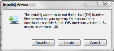
Yes, with the latest (V9) version of the installer the mechanism for handling the downloaded JRE has changed. If a JRE downloaded from REW was used previously it will not be found and needs to be downloaded again. Alternatively an Oracle JRE could be installed, but that needs to be done before running the REW installer again.
If uninstall the previous version and don't install the Oracle JRE, the installer will work?If a JRE downloaded from REW was used previously it will not be found and needs to be downloaded again.
John Mulcahy
REW Author
- Joined
- Apr 3, 2017
- Posts
- 9,393
You can just click the Download button on that message if you want REW to download the runtime rather than have a system-wide Java runtime. A runtime will have to be downloaded from somewhere though.
This is exactly what I wanted.if you want REW to download the runtime rather than have a system-wide Java runtime
I looked at how the component model of inductors and capacitors is calculated. Now differs from the previous version. It seems to me that the previous version showed less than necessary, and this one more than necessary. But this needs to be analyzed in more detail.
John Mulcahy
REW Author
- Joined
- Apr 3, 2017
- Posts
- 9,393
Do you mean should RC12 give a different model to RC11? In some cases, yes, since the bug that could give incorrect model values has been fixed in RC12 as mentioned in the release notes.
Here are measurements of 4 inductors (3 with a core), 3 capacitors and a ceramic resistor on the 12th version. The name of each measurement contains the element value and the measurement frequency on my device. Maybe it will be interesting.
Attachments
-
Impedance open cct.mdat5.7 MB · Views: 97
-
Impedance ref cal.mdat5.6 MB · Views: 86
-
Impedance short cct.mdat5.7 MB · Views: 89
-
L1 = 7,220 mH at 120 Hz.mdat3.8 MB · Views: 84
-
L2 = 3,087 mH at 120 Hz.mdat3.8 MB · Views: 73
-
L3 = 0,5632 mH at 1 kHz.mdat3.8 MB · Views: 79
-
L4 = 0,3042 mH at 1 kHz.mdat3.8 MB · Views: 116
-
C1 = 100,87 mkF at 120.mdat5.6 MB · Views: 112
-
C2 = 11,82 mkF at 1 kHz.mdat5.6 MB · Views: 99
-
C3 = 3,863 mkF at 1 kHz.mdat5.6 MB · Views: 96
-
R1 = 2,242 Ohm at 120.mdat3.8 MB · Views: 101
If there are many dimensions in REW, and then delete one by one in order to reduce the saved file for uploading to the forum, then the reduction in size is strange. The original file contains 11 measurements. After removing the first minus 12 MB. After removing the second -5 MB. After removing the 3rd -0 MB. -0 MB. Etc. The last file containing one dimension weighs -15 MB from the original. In my case, 48 MB. It cannot be uploaded to the forum.
John Mulcahy
REW Author
- Joined
- Apr 3, 2017
- Posts
- 9,393
Inductor model fits look good. C3 looks like a well behaved capacitor, C1 and C2 not so much, odd behaviour below 100 Hz.
John Mulcahy
REW Author
- Joined
- Apr 3, 2017
- Posts
- 9,393
The model fit isn't great with any of them other than C3, but I'm not sure about the measurements. I haven't seen capacitor measurements where the phase is as far from 90 degrees through the (relatively) flat portions of the phase response. [Edit:] The odd phase behaviour may be due to dielectric losses, but incorporating them complicates the equivalent circuit. I'll spend some time looking at it.
Last edited:
John Mulcahy
REW Author
- Joined
- Apr 3, 2017
- Posts
- 9,393
I have changed the capacitor component model behaviour for the next build and added an option to model dielectric loss. It provides a more accurate fit to the impedance data, but a more complicated equivalent circuit with no single capacitor value to use. The best option is probably to use the impedance readout value for the capacitance at the frequency of interest.

If use this option like in the second picture, will Csum be 85.5 uF + 4.19 uF = 89.69 uF?an option to model dielectric loss.
John Mulcahy
REW Author
- Joined
- Apr 3, 2017
- Posts
- 9,393
Yes, and I will display a Csum value, but it tends to be valid at a relatively low frequency around 100 - 200 Hz so the impedance readout may still be a better way to pick a single number when required.
The difference between the impedance graphs in the two pictures is very small, however, Csum 86.7 uF and 89.69 uF seem to differ more. Maybe there is a more complex formula for calculating the resulting capacitance (inductance) for cases like in picture 2?
John Mulcahy
REW Author
- Joined
- Apr 3, 2017
- Posts
- 9,393
The problem is that the capacitance varies with frequency. It is easier to read the capacitance at a particular frequency directly off the graph than to calculate the equivalent capacitance of the network that models its behaviour, and more accurate where the model differs from the measurement. For circuit simulation the equivalent circuit components can be substituted for the actual capacitor.Maybe there is a more complex formula for calculating the resulting capacitance (inductance) for cases like in picture 2?
This is your main recommendation. I got it.to read the capacitance at a particular frequency directly off the graph
REW's ability to measure capacitors and inductors, resistors, more precisely than many physical devices, will be fully realized when the user receives, after measurement, a specific figure - the value of an element in its units at the desired frequency. But there is the problem of reading the readings. This is when at 1 kHz L = 562 mH, at 999 Hz L = 563 mH, at 998 Hz again 562 mH at 1001 Hz L = 561 mH, at 1002 Hz L = 562 mH. It's the same with capacitors. Variability of readings is a feature of digital processing (it seems to me) of measurements and cannot be changed. But what is possible is what I suggested earlier. https://www.avnirvana.com/threads/smd-power-inductors-measurements.8901/post-68494
John Mulcahy
REW Author
- Joined
- Apr 3, 2017
- Posts
- 9,393
More likely a feature of measurement noise. Use the impedance measurement noise filter and/or apply a little smoothing.Variability of readings is a feature of digital processing (it seems to me) of measurements and cannot be changed.
That helped. Thank you.apply a little smoothing


Popular tags
20th century fox
4k blu-ray
4k uhd
4k ultrahd
action
adventure
animated
animation
bass
blu-ray
calibration
comedy
comics
denon
dirac
dirac live
disney
dolby atmos
drama
fantasy
hdmi 2.1
home theater
horror
kaleidescape
klipsch
lionsgate
marantz
movies
onkyo
paramount
pioneer
rew
romance
sci-fi
scream factory
shout factory
sony
stormaudio
subwoofer
svs
terror
thriller
uhd
ultrahd
ultrahd 4k
universal
value electronics
warner
warner brothers
well go usa