Question about Impedance Calibration

Helmut Keller

Registered
Thread Starter
Joined
May 19, 2021
Messages
2
I have the following Question regearding the impedance calibration:

Which assumption is true?

A) Only a single real valued calibration factor is used for the correction. It is extacted from the impedance calibraition file at mid frequncies.

B) The complete impedacne calibration file is used for the corection. Each frequency bin is corrected with its own gain and phase value.

C) Sometihng else. If so please clarify it?
 

John Mulcahy

REW Author
Joined
Apr 3, 2017
Messages
7,337
The V5.20 impedance calibration process generates a set of cal files for the open circuit, short circuit and reference resistor calibration steps that apply frequency-dependent gain and phase corrections across the full frequency range.
 

trobbins

Member
VIP Supporter
Joined
Nov 26, 2017
Messages
121
Location
Australia
John, is that impedance calibration able to be separately saved, and then reinstated - like the typical calibration files?
 

John Mulcahy

REW Author
Joined
Apr 3, 2017
Messages
7,337
The 3 cal files are written to the REW log files folder (impedanceopen.zma, impedanceshort.zma, impedancercal.zma) so they could be manually managed, but there isn't a feature to have multiple sets of impedance cal files.
 

trobbins

Member
VIP Supporter
Joined
Nov 26, 2017
Messages
121
Location
Australia
Ta. I only have one impedance 'jig' at the moment so not a big deal from my perspective, especially as the cal process is pretty quick. I guess it could be a benefit for those who want to use different sense resistor values in deferent jigs. I keep the soundcard manual levels the same, but could foresee wanting to vary the soundcard output level for some tests (but haven't run any tests yet to see if that would upset the use of the default calibration).

It is an amazingly versatile and accurate tool :T.

The only extended capability I have come to realise could be to allow a calculated parameter to be plotted versus frequency - for example if the plot was of a part that was inductive over a portion of frequency range, and capacitive over another portion, then at present the magnitude trace can be pointed at to show a calculated value for the inductive/capacitive impedance at that spot frequency, and then other points on the trace can be checked for how the value changes (with a change in inductance/capacitance parameter at zero phase crossings).
 

Helmut Keller

Registered
Thread Starter
Joined
May 19, 2021
Messages
2
I want to use a Rsense of 1 Meg Ohm to measure the impedance of electric guitar pickups.
I guess I would need to short cut Rsense during the open circuit calibration. Other wise the
gain diffrence between left and right channel would be about 6 dB for a 1 Meg Ohm input impedancet at low frequencies and even higher at higher frequencies. I only need a calibration of the gain and phase differences of the two input channels. I can correct the input impedance of the souncard on my own by making an open circuit measurement after gain and phase difference calibration. I do not need a short circuit calibartion due to the high impedance values. Also I don't need a reference resistor calibration. So how can I do my job with version 5.20.

In the moment I use version 5.19. Can you answer my original question also for 5.19.
 

trobbins

Member
VIP Supporter
Joined
Nov 26, 2017
Messages
121
Location
Australia
I'd recommend you definitely update to V 5.20 to use the new cal process. I initially use an Rsense of 100 ohm (not 1Meg) and go through the standard calibration with the clip leads you intended to connect to the PUP - the main issue is to have at least a 1% reference resistor to use in the last part of the calibration sequence (luckily I have a 0.05% 10R, but also have used 1k62 but not a 47k) but clip close to the resistor body to avoid extra inductance issues (especially if you have a 192kHz sampling soundcard and want to use bandwidth to 96kHz). As verification, measure a 10k and 1Meg resistor to confirm they are correctly 'measured' over the audio bandwidth. That has accurately worked for me for chokes and inductors (I don't have a sample PUP with me to test). You should see an inductive low frequency portion reaching a main resonance and then going capacitive.
 

trobbins

Member
VIP Supporter
Joined
Nov 26, 2017
Messages
121
Location
Australia
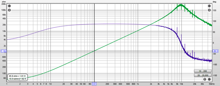
I only have a few plots of chokes I have recently tested for main frequency rectified power supplies. Choke is from a 20W flourescent ballast - not large but not as small as a PUP, and the core is obviously different, but from what I have seen of PUPs and measurements, they will have a significantly higher lower frequency resistance, but will have substantial self capacitance, and so would likely show a resonant peak well within a 96kHz range (but OP may not be able to go that high). Unfortunately my son has all his guitar gear in another city so I can't make a quick sample measurement, but I recall people have made impedance measurements manually over the decades.
Atco EC18-20 impedance.png
 

sm52

Member
Joined
Mar 14, 2019
Messages
892
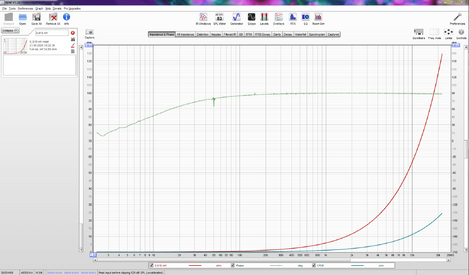
Why did I ask? I do not see the transition from inductive to capacitive. I read this happens at very high frequencies, not audio frequencies. For example, the impedance of the inductor 0.918 mH.
 

Attachments

  • 0.918 mH.PNG
    0.918 mH.PNG
    108.9 KB · Views: 7

trobbins

Member
VIP Supporter
Joined
Nov 26, 2017
Messages
121
Location
Australia
It will depend on how much self-capacitance (shunt capacitance) is in the inductor. My recollection is that PUPs have a significant self-capacitance, as the winding has lots of turns of small gauge wire in close proximity. A quick google shows many people are interested, although few if any show an impedance response - this link gets close eg. https://www.syscompdesign.com/wp-content/uploads/2018/09/guitar-pickups.pdf
 

sm52

Member
Joined
Mar 14, 2019
Messages
892
According to your link, the resonance is about 100 kHz. As I expected.
 

trobbins

Member
VIP Supporter
Joined
Nov 26, 2017
Messages
121
Location
Australia
I think you were looking at the frequency response - look at the section before where it indicates an example PUP has L=8H and Cshunt about 60pF - hence about 7kHz impedance resonance.
 

sm52

Member
Joined
Mar 14, 2019
Messages
892
Okay. I didn't investigate in any detail this question regarding guitars. If we talk about inductors in crossover circuits for acoustics, then it makes no sense to take into account the resonance of the coil. Good luck.
 

John Mulcahy

REW Author
Joined
Apr 3, 2017
Messages
7,337
I want to use a Rsense of 1 Meg Ohm to measure the impedance of electric guitar pickups.
I guess I would need to short cut Rsense during the open circuit calibration. Other wise the
gain diffrence between left and right channel would be about 6 dB for a 1 Meg Ohm input impedancet at low frequencies and even higher at higher frequencies. I only need a calibration of the gain and phase differences of the two input channels. I can correct the input impedance of the souncard on my own by making an open circuit measurement after gain and phase difference calibration. I do not need a short circuit calibartion due to the high impedance values. Also I don't need a reference resistor calibration. So how can I do my job with version 5.20.
Do not short Rsense during the open circuit calibration. You do not have to go through all 3 calibration steps, but the result will be a lot more accurate if you do.

In the moment I use version 5.19. Can you answer my original question also for 5.19.
V5.19 only corrects for channel gain difference at around 316 Hz.
 
Top Bottom