jesperlykke
New Member
Thread Starter
- Joined
- May 26, 2020
- Posts
- 23
Hello all.
A long time user on diyaudio, lead me to here to get hopefully answer to a quistion(s) i have. (User lykkedk @ diyaudio.com)
Recently i "build" a setup to measure amplifier etc. harmonics, noise and so.
It's been some journey, but i'am getting good results.
The build is based on a modded Behringer soundcard, which is modded with a balanced input, acepting amplifier input directly, without use of voltage dividers.
I'am trying to use a notch filter, along with my internal generator / external 1kHz sine osc. and / or measuring amplifier's.
Reason i build the notch is to have much lower input's on the Behringer, hopefully getting even better result's.
I will explain what i did for using it for now.
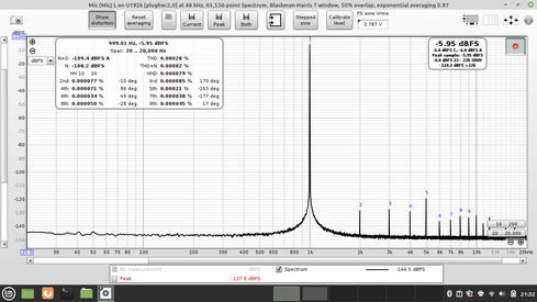
* With input-level at MAX.
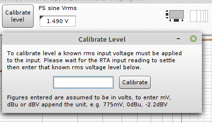
* Set genreator at known voltage, and calibrate REW to that in the "Generator" dialog.
* Verify, using RTA with "V" that the voltage is correct.
* Make a sweep and save this as "SoundCard" (Generator out ---> Behringer in)
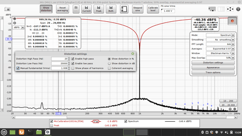
* Then i connected my notch (Generator out ---> Notch ---> Behringer in) - Make a sweep and save as Notch1KHz
* Next trace arethmetic (Notch / SoundCard), and Save/Export as mic.Calibration file.
* Load mic. calibration file,
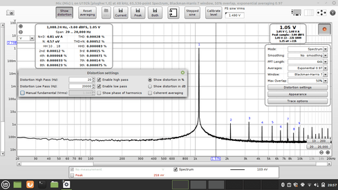
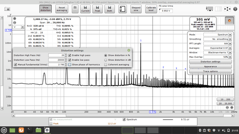
* With external osc. set at a known voltage (E.g. 1008mV) feed like this (1KHz-external ---> Notch ---> Behringer)
(This could be at -3dB, just befor the soundcard starts to clip)
* Plug in the fundamental in the dialog at RTA to this known voltage (1.008V)
Now REW show's the correct number's and everything seem's allright.
It's seems to be very good, also when measuring through an poweramplifier. (External osc. ---> Poweramp. ---> Notch ---> Behringer)
If i set the output of the poweramp. to around the same voltage as the fundamental (1008mV) the dB shows correct numbers (Rightside, Top on RTA window), and again everything seems perfect.
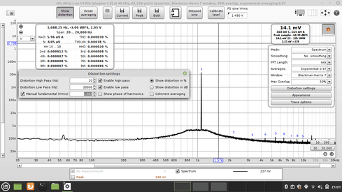
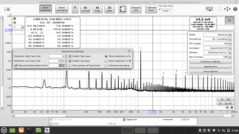
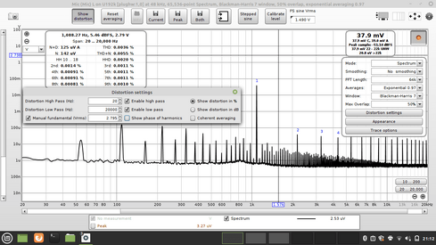
But if i then set the amplifier output to say 2.800V for measuring at around 1w, the dB is going positive. (Could end up at maybee 5.6dB or so) (EDIT :: and setting the fundamental to this value ofcause)
This is because the FS sine Vrms is set to the calibrated level at -3dB i guess.
How do i handle this? I cannot figure it out guy's
I think it's the only missing parameter i need to know for having it under control
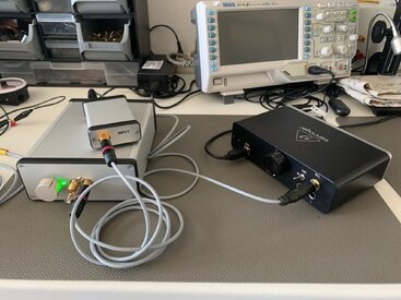
Attached some pictures, with text to describe what it is.
Jesper.
Don't mind if the numbers does not fit with my description. (The USB-PC-6dB is a typical "loopback" with external osc.)
A long time user on diyaudio, lead me to here to get hopefully answer to a quistion(s) i have. (User lykkedk @ diyaudio.com)
Recently i "build" a setup to measure amplifier etc. harmonics, noise and so.
It's been some journey, but i'am getting good results.
The build is based on a modded Behringer soundcard, which is modded with a balanced input, acepting amplifier input directly, without use of voltage dividers.
I'am trying to use a notch filter, along with my internal generator / external 1kHz sine osc. and / or measuring amplifier's.
Reason i build the notch is to have much lower input's on the Behringer, hopefully getting even better result's.
I will explain what i did for using it for now.
* With input-level at MAX.
* Set genreator at known voltage, and calibrate REW to that in the "Generator" dialog.
* Verify, using RTA with "V" that the voltage is correct.
* Make a sweep and save this as "SoundCard" (Generator out ---> Behringer in)
* Then i connected my notch (Generator out ---> Notch ---> Behringer in) - Make a sweep and save as Notch1KHz
* Next trace arethmetic (Notch / SoundCard), and Save/Export as mic.Calibration file.
* Load mic. calibration file,
* With external osc. set at a known voltage (E.g. 1008mV) feed like this (1KHz-external ---> Notch ---> Behringer)
(This could be at -3dB, just befor the soundcard starts to clip)
* Plug in the fundamental in the dialog at RTA to this known voltage (1.008V)
Now REW show's the correct number's and everything seem's allright.
It's seems to be very good, also when measuring through an poweramplifier. (External osc. ---> Poweramp. ---> Notch ---> Behringer)
If i set the output of the poweramp. to around the same voltage as the fundamental (1008mV) the dB shows correct numbers (Rightside, Top on RTA window), and again everything seems perfect.
But if i then set the amplifier output to say 2.800V for measuring at around 1w, the dB is going positive. (Could end up at maybee 5.6dB or so) (EDIT :: and setting the fundamental to this value ofcause)
This is because the FS sine Vrms is set to the calibrated level at -3dB i guess.
How do i handle this? I cannot figure it out guy's
I think it's the only missing parameter i need to know for having it under control
Attached some pictures, with text to describe what it is.
Jesper.
Don't mind if the numbers does not fit with my description. (The USB-PC-6dB is a typical "loopback" with external osc.)
Attachments
Last edited:
") )
)