Eric SVL
Member
- Joined
- May 1, 2017
- Posts
- 173
More
- Preamp, Processor or Receiver
- Denon AVR-X4500H
- Main Amp
- Hypex NCore NC252MP
- DAC
- Micca OriGen G2
- Computer Audio
- iLoud MTM
- Universal / Blu-ray / CD Player
- Sony PS3, PS4
- Streaming Equipment
- Google Chromecast
- Streaming Subscriptions
- GIK Tri-Traps
- Front Speakers
- Buchardt S400
- Surround Speakers
- Polk LSiM 702
- Front Height Speakers
- Focal Chorus OD 706 V
- Rear Height Speakers
- Focal Chorus OD 706 V
- Subwoofers
- Rythmik
- Other Speakers
- ELAC Debut Reference DFR52
- Screen
- Samsung PN64H5000
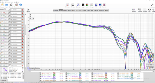
Based on my experience with Dirac Live, which does not have an equal loudness function like Audyssey, bass levels overpower the system if I go past my normal listening levels. I believe there definitely is a flattening out of the needed bass levels as volume increases. Low levels always require the most bass boost to achieve perceived spectral balance. The reality would seem to be somewhere in between the red and blue lines.It was 1933 Noah, I wonder if anything other than Sines were available. I am suggesting that it takes a while for the curve of sensitivity to establish when the overall volume is changed. But I an reconsidering even that now, due to finding the following. To be honest I hadn't taken any notice of this until just now.
It appears a lot of our assumptions that we hear best and flattest at high levels are probably mistaken.
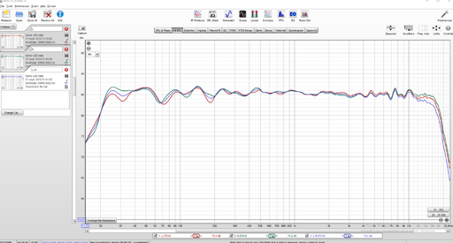
Fletcher Munson's work has been improved on with very different results. This graph suggests to me that the spectra we hear at different volumes, particular at commonly occurring levels, don't vary much at all.
View attachment 32817


 ).
).
")