REW Beta Release Impedance measurement accuracy

Thread Starter
Joined
Feb 8, 2018
Messages
279
Location
Italy
Good evening Mr. Jhon, I would like some advice on how to improve the accuracy of the impedance measurement.
I have created a measuring instrument based on its REW software and i am currently realizing a second release of the instrument with the best precision and extent of measurement.
To make measurements with good precision, i use a high impedance buffer at the input of the sound card with a multi-turn adjustment trimmer in order to perfectly balance the level between
the right and left channel so as not to have to do the software calibration of REW.
Before making the impedance measurement of a device (passive component) I measure the output cable in short and the output cable open to check the impedance at zero ohms and in theory infinite
(in practice, about input impedance of the buffer ).
Precisely the open circuit measurement creates some precision problems on the measurement since it is very variable and I can't give myself an explanation as to why this behavior.
I attach the files so that I can also see the current accuracy of the measurement.

Thank you for everything and congratulations on your beautiful software that allowed me to build the ideal tool for my electro-acoustic projects.
 

Attachments

  • Impedenza_circuito_aperto.mdat
    4 MB · Views: 16
  • Impedenza_circuito_chiuso.mdat
    4 MB · Views: 5
  • Impedenza_resistenza_test_10ohm.mdat
    4 MB · Views: 8
  • Impedenza_resistenza_test_111ohm.mdat
    4 MB · Views: 3
  • Impedenza_resistenza_test_150ohm.mdat
    4 MB · Views: 4
  • Impedenza_resistenza_test_300ohm.mdat
    4 MB · Views: 4
Thread Starter
Joined
Feb 8, 2018
Messages
279
Location
Italy
From the open circuit impedance curve it is possible to see that the value is very low at the extremes of the band while at 100 band it is equal to the input impedance
value of the buffer which is 90K ohm. I do not explain this trend and I think this is the problem of the May measurement error at the extremes of the band, in particular
at low frequency the 20 Hz starts to increase the error specifically if a component with high values is measured. See misuara with R test at 300 ohms.

Can you clarify this behavior for me?
 

John Mulcahy

REW Author
Joined
Apr 3, 2017
Messages
7,212
The general approach used in REW is OK up to a few hundred or perhaps a few thousand ohms, frequency-dependent variability in the soundcard's input impedance and frequency-dependent variability in the differences between channels mean it doesn't work well for higher impedances - open circuit being an extreme example. There is a good discussion of that in ARTA's LIMP user manual. A much more elaborate calibration process and measurement compensation would be required to try and deal with that.
 

John Mulcahy

REW Author
Joined
Apr 3, 2017
Messages
7,212
Note that soundcard inputs are typically AC coupled so differences between the coupling capacitors in each channel also have an influence.
 
Thread Starter
Joined
Feb 8, 2018
Messages
279
Location
Italy
I know Arta quite well I used it a few years ago before choosing REW because it worked well on linux and Arta worked only on Window or via wine emulation but not on Raspberry.
If you have had the chance to see the measurements you will certainly have realized the good precision especially with impedance values of 10 ohms at the center band we are in the order of 0.2% while below 10 Hz we are - 1%. Maybe you're right when you say that the calibration algorithm should be improved to compensate, it could be a future improvement to make REW even better. For example I remember that on ARTA the LIMP module besides taking into account the resistance of the cables could also compensate for the inductance this could be easily implemented in REW.
Another thing that comes to mind to improve measurement accuracy is to increase the accuracy of the Rsense value, instead of a digit after the comma it could make sense to have two.
Is it possible to disable impedance calibration? I need to disable this function to be able to electronically align the two channels ..

Sorry if I take advantage of your availability, thank you very much ..
 

John Mulcahy

REW Author
Joined
Apr 3, 2017
Messages
7,212
The impedance cal approach changed in LIMP recently.

When you say "disable the impedance cal" do you mean go back to an uncalibrated state? You could delete REW's preferences (there is an entry in the Preferences menu) though that removes all preferences. It isn't necessary for channel alignment though, the impedance cal has no effect on the input levels REW displays, only on the impedance calculation. It can just be repeated after you trim the channels. Channel trim is not necessary for REW's impedance measurement since the calibration process accounts for any gain mismatch between the channels.

You can check the relative gain and phase between the input channels using the displays on the REW Levels tool when playing a sine wave on the REW generator.
 
Thread Starter
Joined
Feb 8, 2018
Messages
279
Location
Italy
I made the calibration measurement by first taking the right channel as a reference and then the left. There are very small differences ( 0,1 -0,2 db ) that could be the cause of the lowering of the impedance to the extremes of the band. If so, this difference should be compensated for when calculating the impedance value so as to have a much more correct measurement.
What do you think about it ?
 

Attachments

  • Soundcard_LoopBack_CH_L_Input_CH_R.mdat
    6.1 MB · Views: 5
  • Soundcard_LoopBack_CH_R_Input_CH_L.mdat
    6.1 MB · Views: 3
Thread Starter
Joined
Feb 8, 2018
Messages
279
Location
Italy
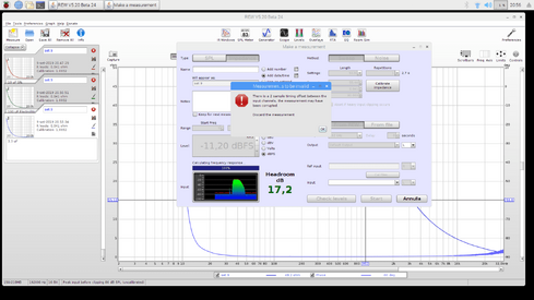
When measuring the REW inductance it performs well, I attach the measurement made with a 1 mH coil with a 0.55 ohm resistance. Instead I have some doubts about the measure of the capacity especially with regards to the phase that has a trend for most of the curve at -90 degrees. Also the capacity measure is the program from an error.
I am attaching the files.
thank you
 

Attachments

  • Impedenza_induttanza_1mH.mdat
    4 MB · Views: 5
  • Impedenza 10uF not electrolitic.mdat
    2.5 MB · Views: 5
  • Impedenza 100uF Electrolitic not pol.mdat
    2.5 MB · Views: 4
  • Impedenza 3uF electrolitic not polarized.mdat
    1.7 MB · Views: 5
  • Impedenza 3_3uF not electrolitic.mdat
    1.7 MB · Views: 6
  • Error_Impedenza_Capacitor.png
    Error_Impedenza_Capacitor.png
    92.7 KB · Views: 27
  • roomeq_wizard9-9-2019.log.txt.zip
    1.1 KB · Views: 4

John Mulcahy

REW Author
Joined
Apr 3, 2017
Messages
7,212
I made the calibration measurement by first taking the right channel as a reference and then the left. There are very small differences ( 0,1 -0,2 db ) that could be the cause of the lowering of the impedance to the extremes of the band. If so, this difference should be compensated for when calculating the impedance value so as to have a much more correct measurement.
What do you think about it ?
Yes, differences between the channels affect the measurement. Both channels are measured during the impedance calibration process, the difference between them over a band around 1 kHz is used in the current calibration correction. Other ways of compensating for the behaviour captured during the impedance calibration are on the todo list to investigate at some point.
 
Thread Starter
Joined
Feb 8, 2018
Messages
279
Location
Italy
The variation between 0 and -90 degrees is OK but the trend with which it takes place does not convince me. Go from 0 to around -90 degrees almost immediately and then stay at around -90 for a long time. Does it seem regular? In the measure of the inductance the behavior is much more convincing ...
 
Thread Starter
Joined
Feb 8, 2018
Messages
279
Location
Italy
Then in the measurement with the capacitor it always gives me the error I sent you. Does it seem regular?
 

John Mulcahy

REW Author
Joined
Apr 3, 2017
Messages
7,212
Then in the measurement with the capacitor it always gives me the error I sent you. Does it seem regular?
Probably a side effect of measuring at 192 kHz, the purely capacitive impedance is shifting the impulse response peak on the measurement channel enough to trigger the message.
 
Thread Starter
Joined
Feb 8, 2018
Messages
279
Location
Italy
I re-checked the phase of the circuit consisting of Rsense and Capacitance of 10uF not electrolitic this time carrying out a level measurement (SPL) and the measured phase
is perfectly in line with the theory, in fact at the cutoff frequency -3db is -45 degrees .
I apologize for the evaluation error, so this means that REW works well.
Thank you
 

Attachments

  • Misura SPL Rsense 10uF.mdat
    4.9 MB · Views: 4
Top Bottom