Impedance Measure Diagram

Porx73

Registered
Thread Starter
Joined
Sep 3, 2017
Messages
2
Hi All,
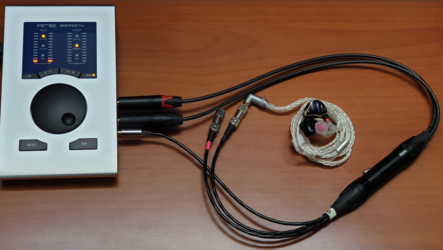
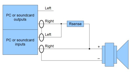
I would like to build a cable like the one in the photo, for measuring the impedance of the IEM's. Could you help me understand how to modify the diagram that REWHelp recommends in the case of a stereo IEM's measurement?
Thanks
 

Attachments

  • Schermata 2024-02-03 alle 09.50.03.png
    Schermata 2024-02-03 alle 09.50.03.png
    311.4 KB · Views: 13
  • Schermata 2024-02-04 alle 11.33.12.png
    Schermata 2024-02-04 alle 11.33.12.png
    14 KB · Views: 13

sm52

Member
Joined
Mar 14, 2019
Messages
892
Stereo consists of two channels. Each of them has its own driver. Measure one channel first, for example the left one. Then the right one. You will receive two graphs. Therefore, the diagram from the help is relevant.
 

Porx73

Registered
Thread Starter
Joined
Sep 3, 2017
Messages
2
Stereo consists of two channels. Each of them has its own driver. Measure one channel first, for example the left one. Then the right one. You will receive two graphs. Therefore, the diagram from the help is relevant.

Stereo consists of two channels. Each of them has its own driver. Measure one channel first, for example the left one. Then the right one. You will receive two graphs. Therefore, the diagram from the help is relevant.
on the sound card I use the headphone output which is stereo and in the cable there are 2 headphone outputs one for L and one for R.
I don't understand how to adapt the diagram, which only includes a speaker to build the cable in the photo.
 

John Mulcahy

REW Author
Joined
Apr 3, 2017
Messages
7,337
The speaker in the diagram represents the load being measured, for IEMs that would be one of the channels. If you want to measure the impedance of each channel separately you will need an adaptor to link to the particular channel you want to measure.
 
Top Bottom