


-
AUDIO VIDEO PROCESSING, SETUP & ENVIRONMENTOfficial REW (Room EQ Wizard) Support Forum Audiolense User Forum Calibration Equipment Auto-EQ Platforms / Immersive Audio Codecs Video Display Technologies / Calibration AV System Setup and Support Listening Room / Home Theater Build Projects Room Acoustics and Treatments AV Showcase Movies / Music / TV / Streaming
-
AUDIO VIDEO DISCUSSION / EQUIPMENTHome Theater / Audio and Video - Misc Topics Essence For Hi Res Audio AV Equipment Advice and Pricing Awesome Deals and Budget AV Equipment AV Receivers / Processors / Amps UHD / Blu-ray / CD Players / Streaming Devices Two Channel Hi-Fi Equipment DIY Audio Projects Computer Systems - HTPC / Gaming HD and UHD Flat Screen Displays Projectors and Projection Screens AV Accessories Buy - Sell - Trade
Navigation
Install the app
How to install the app on iOS
Follow along with the video below to see how to install our site as a web app on your home screen.
Note: This feature may not be available in some browsers.
More options
You are using an out of date browser. It may not display this or other websites correctly.
You should upgrade or use an alternative browser.
You should upgrade or use an alternative browser.
How to measure the STC with REW?
- Thread starter peterandu
- Start date

Matthew J Poes
AV Addict
- Joined
- Oct 18, 2017
- Posts
- 1,905
The AudioTools app can give you a reading of the STC results after finishing two measurement within the studio and outside the studio.
Does REW have a similar feature?
This is the AudioTools tutorial video
It’s not automated but it can be done manually. There is no advanced calculations.
http://arnisco.com/astm/PDF/E336.PDF
This paper provides the procedure you need to follow and puts AudioTools method into context.
I’ve been developing my own protocol for doing this using REW and an external excel worksheet I created. I also have the AudioTools app.
I’m curious what hardware you are using to do this. I finally had to breakdown and spend a small fortune on new hardware because the transmission loss of my partitions was so high that I was unable to produce a loud enough test signal to capture that signal through the wall. Instead I just got noise. I’m still having problems but am closer than I’ve ever been.
I use two iOS devices with audio tools for the test signals. I use a mix of pink noise and pure tones. One is the generator and the other is the remote. I need this because playing 120dB for long periods of time introduces compression after a while. I then use my laptop with a Motu 828x and a NIST traceable mix with 15dB of self noise. First I measure in the room while running the mic out of the room and wearing hearing protection. I take a spatial average over about 30 seconds. Then I move the measurement rig out of the source room and into the receiver room and measure again. I take 1/3 octave RTA measurements for both. I also take 1/3 octave noise floor measurements of both to ensure I am never measuring just noise. I export the values at each 1/3 octave value and the difference between the two is the TL. I then calculate STC based on that relative to the STC curves.
At the moment I’m still measuring noise at most frequencies above 300hz so the tests haven’t been successful enough to confirm everything is working. This is true of the AudioTools app as well however.
luegotelodigo
New Member
- Joined
- Nov 2, 2018
- Posts
- 40
In my village we have a saying: It's not the arrow, it's about the indian.I’m curious what hardware you are using to do this. I finally had to breakdown and spend a small fortune on new hardware because the transmission loss of my partitions was so high that I was unable to produce a loud enough test signal to capture that signal through the wall. Instead I just got noise.
You can achieve good results measuring high insulations with sweeps and cheap gear following the ISO 18233. I think the only thing REW can't do is filtering the impulse response according to IEC.
Matthew J Poes
AV Addict
- Joined
- Oct 18, 2017
- Posts
- 1,905
The Article I linked discusses the purpose of the impulse measurement and REW can absolutely do that. You just need a sound source. I recently learned it can directly import a direct impulse measurement, so you can use a clapper or balloon pop.
As for cheap gear, that isn't my experience. Cheap gear has a very high noise floor, typically unable to measure much below 25-45dB depending on what we are talking about. USB measurement mics are VERY noisy. If you can't measure to below the noise floor of the receiver room, then you would need the sound source to be VERY loud to be loud enough to be detected over the mic's noise.
I'm still having this problem. My walls were built to an STC 80 spec, that means I need a 120dB sound source to reliably detect that above the noise floor of the receiver room. More so if I use a noisy mic. My experience has been that noisy mics are just not adequate (same with SPL meters). There is no magic the user can do to fix this, you can't get rid of that noise. The standard method relies on 1 octave or 1/3 octave RTA, so there is no noise canceling that can be achieved.
luegotelodigo
New Member
- Joined
- Nov 2, 2018
- Posts
- 40
Please don't do that...I recently learned it can directly import a direct impulse measurement, so you can use a clapper or balloon pop.
My walls were built to an STC 80 spec, that means I need a 120dB sound source to reliably detect that above the noise floor of the receiver room. More so if I use a noisy mic.
No you don't need such SPL. If you take a look at the ISO 18233 you will discover the concept of "effective signal-to-noise ratio".
You sweep 20 to 20K in let's say 10 seconds and REW deconvolves it into a delta function that has an improved SNR because all the energy your loudspeaker radiates in 10 seconds is zipped into a few samples. I've used this technique to measure loudspeakers below the background noise. I'd suggest you to read some papers (Müller-Massarani and Farina have good ones).
How do you think they measured -20 dB at Microsoft anechoic chamber with a pair of 1/2" mics if their noise is higher than 5 dBA?My experience has been that noisy mics are just not adequate (same with SPL meters). There is no magic the user can do to fix this, you can't get rid of that noise.
I insist it's not the arrow what matters.
Matthew J Poes
AV Addict
- Joined
- Oct 18, 2017
- Posts
- 1,905
They measured those levels at microsoft because the noise floor of a mic is not constant and they make lab mics that are that quiet. Not because of noise processing.
You can't use a sweep outside the test room nor does the ISO 18233 standard state that. You won't pick up the sweep through the wall.
I was trained on how to do this in an academic setting (University of Illinois) by an acoustical engineer and what you have described isn't what he taught me.
What I was trained is that you must have a noise source that is 10dB's above the room noise floor in the receiver room. They taught me to calculate this by taking the expected maximum SPL TL and add 10dB's to that. Then Add that value to the room noise floor and that is the volume I need for the source. In my case, 120dB's puts me in the ballpark. At high frequencies I can't actually achieve the level I need, since an STC 80 room has more than 100dB's of TL at higher frequencies and my receiver room has a noise floor in excess of 20dB's at those frequencies.
As for the clapper, not sure your problem with it. It's an industry standard approach. These are omni-diretional sources with relatively full frequency response. Nothing wrong with it. It's more accurate than using a single speaker and a sweep, if that is what you intend to do. That would be the wrong way to do it.
luegotelodigo
New Member
- Joined
- Nov 2, 2018
- Posts
- 40
That's not true. They used coherent power measurement in Labshop…which is available as a function when you turn on the cross power spectrum for the FFT or the CPB. In few words, the coherent power measurement eliminates thermal noise inerrant from the microphone self-noise. After 2-3 minutes the coherent spectrum is used to compute an overall level in dB(A).They measured those levels at microsoft because the noise floor of a mic is not constant and they make lab mics that are that quiet. Not because of noise processing.
You must be kidding, ISO 18233 complete title is "Application of new measurement methods in building and room acoustics" it would be funny if you can't use it in building or room acoustics.You can't use a sweep outside the test room nor does the ISO 18233 standard state that. You won't pick up the sweep through the wall.
I've been lecturing about this for 10 years in a Masters degree in acoustics engineering and what I describe is part of what I teach.I was trained on how to do this in an academic setting (University of Illinois) by an acoustical engineer and what you have described isn't what he taught me.
I know a great guy who got a PhD using that kind of techniques and they were cool back in the sixties but do you really think repeatability or SNR aren't serious issues?As for the clapper, not sure your problem with it. It's an industry standard approach.
Matthew J Poes
AV Addict
- Joined
- Oct 18, 2017
- Posts
- 1,905
That's not true. They used coherent power measurement in Labshop…which is available as a function when you turn on the cross power spectrum for the FFT or the CPB. In few words, the coherent power measurement eliminates thermal noise inerrant from the microphone self-noise. After 2-3 minutes the coherent spectrum is used to compute an overall level in dB(A).
You must be kidding, ISO 18233 complete title is "Application of new measurement methods in building and room acoustics" it would be funny if you can't use it in building or room acoustics.
I've been lecturing about this for 10 years in a Masters degree in acoustics engineering and what I describe is part of what I teach.
I know a great guy who got a PhD using that kind of techniques and they were cool back in the sixties but do you really think repeatability or SNR aren't serious issues?
Alright well you appear to know more than I. I didn’t think AudioTools worked the way you are saying. I have the same software and module. I thought he impulse convolution was only done in the receiver room. I was taught this long ago enough that method would have been just released so I’m probably out of date. I didn’t realize things had advanced.
I’ve tried the SS method with REW and I just get errors that the level is too low. I do agree (obviously) that this method would lower the noise floor, but I didn’t think it was possible without a very high excitation level. The spaces where i would typically need to measure this would usually have very high sound transmission loss between partitions. By 1khz it would exceed 100dB in most cases.
As for the clapper. You are completely right, but don’t you need to weigh that against the errors you get from a highly directional sound source? Of course an Omni-speaker is the right way to do that, but I assumed you didn’t have that. I don’t, it’s too expensive and my need is too low. The reports I’ve read and my own experience has been that highly directional sources in small rooms causes a bias in the decay rates, they are higher than with an Omni-source.
You will have to share more about this technique for reducing mic noise. I wasn’t aware of any approach that allowed you to use an industry standard method of measuring noise floor (as is used for NC or NCB or PNC or the like) that could lower the mics selfnoise. I’m assuming this isn’t something REW can do. What software packages have this that are cheap or low cost?
I asked B&K once how MS measured their room. They sent me the specs of the hardware and name of the software. I remember the mic had a self noise below 0dB. I think like -5 if I recall. My own mic has a self noise around 15dB and the noise appears mostly at LF’s.
Matthew J Poes
AV Addict
- Joined
- Oct 18, 2017
- Posts
- 1,905
Can you share more about how the ISO method described works in practice. I just downloaded and read the standard. It isn’t the one I was familiar with.
Do you take a SS recording in the source room and then another in the receiver room. When you create the impulse, you console the source room recording rather than the original signal. Construct a transfer function of the wall?
If that is right, how do you get a sufficiently loud transmission through the wall to do that?
I was asked recently if I could provide in situ STC calculation for a home theater shop. I said I would work on it but wasn’t really qualified to do so. I had been testing this with my own theater and not making great progress. Seems like this method would work better, but it was one of the first I tried and it failed. My idea was to record the impulse response with a SS separately in the two rooms and divide them to get a difference. When I attempted to record the receiver room impulse worth REW it gave an error. That was with a playback level of 100dB in the source room. I just assumed it was a dumb idea and impossible.
I also assume this avoids the need for a separate analysis of the receiver rooms decay time.
luegotelodigo
New Member
- Joined
- Nov 2, 2018
- Posts
- 40
Sorry but I don't know about audiotools. My suggestion is to use REW (longest sweep and higher bitrate) and of course in the receiving room you should get a warning message but it doesn't mean you don't get enough "effective SNR". You check that after in the filtered IR window. If you need more SNR you can use longer sweeps with Voxengo Deconvolver for example. The right way to do it is with spatial averaging and depending on the parameter you want to calculate you may need the receiving room's RT. I don't use REW too often but it should work. I used this technique with Norsonic analyzers (121 and 140) and 100 dB decays wasn't a problem, the head of the ISO working group for 18233 works in Norsonic.
Dodecahedrons are omnidirectional as daisies are round. The problem measuring insulation is not the decay rate but the direct radiation from the source. Standards are intended for diffuse fields and there are always sources of uncertainty.
To use the cross power spectrum typically you need a 2 channel analyzer and a pair of mics placed together. For Microsoft anechoic I think they used B&K 4955 (5 dBA noise). If you don't have the analyzer you can record the signals and use Matlab. The noise of a microphone is V shaped, in one end thermal noise prevails and electrical in the other.
https://aip.scitation.org/doi/pdf/10.1063/1.1149785
Matthew J Poes
AV Addict
- Joined
- Oct 18, 2017
- Posts
- 1,905
Sorry but I don't know about audiotools. My suggestion is to use REW (longest sweep and higher bitrate) and of course in the receiving room you should get a warning message but it doesn't mean you don't get enough "effective SNR". You check that after in the filtered IR window. If you need more SNR you can use longer sweeps with Voxengo Deconvolver for example. The right way to do it is with spatial averaging and depending on the parameter you want to calculate you may need the receiving room's RT. I don't use REW too often but it should work. I used this technique with Norsonic analyzers (121 and 140) and 100 dB decays wasn't a problem, the head of the ISO working group for 18233 works in Norsonic.
Dodecahedrons are omnidirectional as daisies are round. The problem measuring insulation is not the decay rate but the direct radiation from the source. Standards are intended for diffuse fields and there are always sources of uncertainty.
To use the cross power spectrum typically you need a 2 channel analyzer and a pair of mics placed together. For Microsoft anechoic I think they used B&K 4955 (5 dBA noise). If you don't have the analyzer you can record the signals and use Matlab. The noise of a microphone is V shaped, in one end thermal noise prevails and electrical in the other.
https://aip.scitation.org/doi/pdf/10.1063/1.1149785
Thanks. I'm going to test this. With REW, that warning means it doesn't record anything. However, there is another option, You can export the sine sweep as a wave file and then record it. In fact, I could run mics between the two rooms and record the sweep at the same time at the two mics through a basic 2 channel recorder. Those could be loaded into REW in one of two ways. First, you could convolve them with the original sweep, which gives the transfer function for each room separately. You could then divide the two and that gives you a difference response (the transfer function of the wall and the transmission loss). You could also divide the receiver room wav with the source room wav instead of the original sweep file and that should give you the transfer function of the loss through the wall. I want to try this. I happen to have two identical Dayton measurement mics, so I should be able to do this.
My lab grade mic is a single, I don't have a pair, and I assume you couldn't really do this with mismatched mics. I thought about measuring each room separately, and that might work fine too. I was a little worried about small differences in the capturing of the sweep that could corrupt the response, but if we followed my later comment and averaged multiple sweeps, those small errors would be negligible I imagine.
I've looked for implementations of this, but it seems like almost none of the commercially available softwares have implemented this protocol. They all use the old one I was familiar with. Norsonic and B&K are among the ones I found that do implement it, and a few others out of Denmark that developed the protocols for B&K. The company I bought my mic from sells and rents Norsonic, so I may ask them.
As for the cross power and MS, I looked into it more myself. They used B&K's software, which I don't have. The mic they used has a self noise of -5dB broadband and -15dB in the audio band. I emailed my contact at B&K, but from what I can tell from the literature, this method improves the signal to noise ratio dramatically, but it does not eliminate the self-noise. That if you need quiet, you still need a very quiet mic to begin with. I did see that it has been used (using B&K mics) in a domestic home theater setting, but that person had B&K do the measurements on site. I don't have those tools. I am going to look into Matlab and two mics, but I need to better understand how much improvement this achieves. One study suggested just 10-15 dB's. If that is so, the self noise of the Dayton mic is 25-30dB. My current mic is quieter than that, so I would really want to be sure this is worth the effort.
dodecahedron speakers are common, but I don't have one. In my area around Chicago, I know of no acousticians that work with domestic sound testing that own them either. I know only of large firms that use them. They typically cost in excess of 5 grand. All of my comments were based on the assumption that you too did not have a dodecahedron speaker. It isn't common at this level of work.
Some of the work I found on this approach for TL suggested an omni-source is not needed and instead used standard directional speakers located in the far corner of the room. While this isn't necessarily what the ISO standard states, they seemed confident in the results. It seems reasonable and more doable for something like a home theater or even a small low budget studio/mastering room.
Your comment about the spatial averaging, I saw reference to this being a problem with the method. The studies suggested it wasn't possible, though some authors noted what I would have thought, that you can just take multiple sweeps at different locations and average them. A vector average may be possible, which retains all the information in the impulse in the average.
Matthew J Poes
AV Addict
- Joined
- Oct 18, 2017
- Posts
- 1,905
Oh and I want to say, thank you for turning me onto this. I apologize for arguing earlier, I clearly didn't know what I was talking about and have learned a lot in 48 hours. I was coincidentally dealing with this exact problem. The Signal to noise ratio in every test scenario I had with a sound proof wall was far too low for valid results. I couldn't figure out what to do, other than massively increasing the volume level to dangerously high levels. When you sent this, it was just too perfect a solution and I couldn't believe I hadn't stumbled upon it before (or that people I had asked never brought it up). None the less, its a thing, people do it, and I really want to figure out a solution using readily available tools.
John Mulcahy
REW Author
- Joined
- Apr 3, 2017
- Posts
- 9,387
Funnily enough a question around how to do something like this came up from a user last week. I suggested this, which may work for some circumstances:
Can you run a cable between the rooms? If so you could use REW's acoustic timing reference feature to synchronise to a sweep played back in the other room.
Need one computer capable of playing back a WAV file in the source room, and another running REW in the target room. Also need a speaker (small, just needs to reproduce a tweeter-range timing signal) and amp in the target room.
Save a measurement sweep from the signal generator (select meas sweep on the generator, pick the exact sweep parameters and sample rate you will be using on the measurement computer and click the save button). Put the measurement sweep on the left channel and choose the option to put a timing reference on the right.
Run a cable from the right channel of the playback computer in the source room to your amp/speaker in the target room.
Start an REW measurement in the target room, selecting "Use acoustic timing reference" and ticking the "Wait for timing reference" box under the "Start measuring" button. REW should capture the background noise and then sit showing "Waiting for timing reference...".
Play back the sweep file in the source room
Matthew J Poes
AV Addict
- Joined
- Oct 18, 2017
- Posts
- 1,905
Funnily enough a question around how to do something like this came up from a user last week. I suggested this, which may work for some circumstances:
Can you run a cable between the rooms? If so you could use REW's acoustic timing reference feature to synchronise to a sweep played back in the other room.
Need one computer capable of playing back a WAV file in the source room, and another running REW in the target room. Also need a speaker (small, just needs to reproduce a tweeter-range timing signal) and amp in the target room.
Save a measurement sweep from the signal generator (select meas sweep on the generator, pick the exact sweep parameters and sample rate you will be using on the measurement computer and click the save button). Put the measurement sweep on the left channel and choose the option to put a timing reference on the right.
Run a cable from the right channel of the playback computer in the source room to your amp/speaker in the target room.
Start an REW measurement in the target room, selecting "Use acoustic timing reference" and ticking the "Wait for timing reference" box under the "Start measuring" button. REW should capture the background noise and then sit showing "Waiting for timing reference...".
Play back the sweep file in the source room
I can make it work this way, yes. I have a chase between the theater and the receiver room that allows me to run cables (I could also run them under the door, the rubber gaskets will probably seal around the cables and cause only a slight problem). The chase has plugs on both ends to maintain the soundproofing, but I can pull the plugs and run a cable for this purpose, doesn't take long.
As for the secondary speaker, I can do that as well, I would just grab a small bookshelf and amp or powered monitor.
I assume that you still need to take a measurement in both rooms. Based on your message to me privately, it sounds like it would not be possible to use the room measurement as the source file, so in that case, to derive the transfer function of the wall, you would need to divide the source room into the receiver room IR, and the resultant file would be the wall transfer function. Correct?
luegotelodigo
New Member
- Joined
- Nov 2, 2018
- Posts
- 40
Oops, sorry it's a pity... My suggestion then is to record a long sweep played in your home theater, then in the receiving room and then using Voxengo deconvolver to get 2 impulse responses you will trim and import in REW. I did something similar to measure the noise exposure in a neighbourhood and the PA system was 900 m away...With REW, that warning means it doesn't record anything.
I have tons of gear... tomorrow I'll send you some picturesAll of my comments were based on the assumption that you too did not have a dodecahedron speaker. It isn't common at this level of work.
Matthew J Poes
AV Addict
- Joined
- Oct 18, 2017
- Posts
- 1,905
Oops, sorry it's a pity... My suggestion then is to record a long sweep played in your home theater, then in the receiving room and then using Voxengo deconvolver to get 2 impulse responses you will trim and import in REW. I did something similar to measure the noise exposure in a neighbourhood and the PA system was 900 m away...
I have tons of gear... tomorrow I'll send you some pictures
Thats great, I can only say I'm jealous. I've been looking into it, and for my small acoustics business, its obviously something I SHOULD have, but I can't justify the expense. I do this all as a side job. I don't want to do professional acoustics work, I just like the home theater and small studio side of things, so that has been my focus. The general concerns these clients have (or the builders/contractors) is confirmation measurements and setup. They want to know that the soundproofing worked to the specs they indicated, the acoustics are fine, etc. I can get away without a dodecahedron speaker for that kind of work. Even buying this lab mic was a huge investment for me, but I decided that I needed a better mic with a NIST traceable report as it was requested on some jobs.
I'll look into Voxengo.
John Mulcahy
REW Author
- Joined
- Apr 3, 2017
- Posts
- 9,387
Yes.I assume that you still need to take a measurement in both rooms. Based on your message to me privately, it sounds like it would not be possible to use the room measurement as the source file, so in that case, to derive the transfer function of the wall, you would need to divide the source room into the receiver room IR, and the resultant file would be the wall transfer function. Correct?
Matthew J Poes
AV Addict
- Joined
- Oct 18, 2017
- Posts
- 1,905
Yes.
Ok perfect, I can totally make this work!
luegotelodigo
New Member
- Joined
- Nov 2, 2018
- Posts
- 40
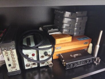
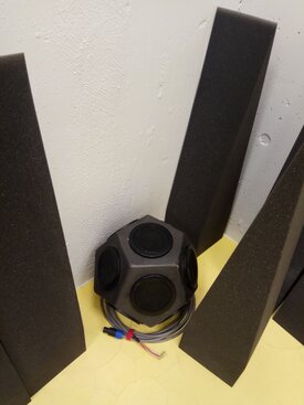
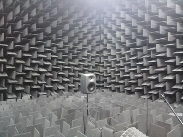
Good morning, a few mics on the shelf, some property of the University and some mine. My dodecahedron (my masters' thesis was designing, building, correcting directivity with acoustic lenses and optimizing frequency response by EQ) I spent around 500 € in materials and it's not too bad. Then the anechoic.
I accumulated a lot of oldies but goldies taking advantage of Ebay (hp 3561A and 239A, Rohde & Schwartz... and if you want to have great cheap microphones you are lucky living in the States. For low noise measurements I have a pair of 4145, you can find those for 100 bucks but when I worked for B&K I checked the price list and they were 2500 € (you'd aso need a power supply and a preamp).
I accumulated a lot of oldies but goldies taking advantage of Ebay (hp 3561A and 239A, Rohde & Schwartz... and if you want to have great cheap microphones you are lucky living in the States. For low noise measurements I have a pair of 4145, you can find those for 100 bucks but when I worked for B&K I checked the price list and they were 2500 € (you'd aso need a power supply and a preamp).
Attachments
Matthew J Poes
AV Addict
- Joined
- Oct 18, 2017
- Posts
- 1,905
Good morning, a few mics on the shelf, some property of the University and some mine. My dodecahedron (my masters' thesis was designing, building, correcting directivity with acoustic lenses and optimizing frequency response by EQ) I spent around 500 € in materials and it's not too bad. Then the anechoic.
I accumulated a lot of oldies but goldies taking advantage of Ebay (hp 3561A and 239A, Rohde & Schwartz... and if you want to have great cheap microphones you are lucky living in the States. For low noise measurements I have a pair of 4145, you can find those for 100 bucks but when I worked for B&K I checked the price list and they were 2500 € (you'd aso need a power supply and a preamp).
All looks very cool. Quite a collection of mics and capsules.
Matthew J Poes
AV Addict
- Joined
- Oct 18, 2017
- Posts
- 1,905
I just wanted to follow up. I managed to get this approach to work fine. Quite well in fact.
The main things i learned was that you gain a lot of S/N, but at higher frequencies, you still need a pretty loud source. I need some longer cords to make all this easier, and when they arrive, I plan to take more measurements again at a higher volume to see how it goes.
The spatial averaging seems really important to get rid of random resonances that would otherwise throw off the results. That is time consuming but doable. I tried it with just three measurements and must have taken a bad one, so I decided not to share that. Again, I'll redo that in the future, being more careful how I take the measurements.
https://www.avnirvana.com/threads/u...on-loss-and-calculate-stc-an-experiment.3638/
luegotelodigo
New Member
- Joined
- Nov 2, 2018
- Posts
- 40
High frequency insulation is huge and it's not a problem. If you don't get enough SNR at highs you get a lower result so your report should state insulation is >= x dB. An useful thing is a flat cable to pass through doors. You need to average spatially but you also need to use 1/3 octave analysis. Low-freq modes are always sources of problems.
The method can be done in steps playing with in-out levels to achieve bigger SNR but I'd prefer to keep it simple. I have some duties right now but I think I'll give it a try in December
The method can be done in steps playing with in-out levels to achieve bigger SNR but I'd prefer to keep it simple. I have some duties right now but I think I'll give it a try in December
Matthew J Poes
AV Addict
- Joined
- Oct 18, 2017
- Posts
- 1,905
High frequency insulation is huge and it's not a problem. If you don't get enough SNR at highs you get a lower result so your report should state insulation is >= x dB. An useful thing is a flat cable to pass through doors. You need to average spatially but you also need to use 1/3 octave analysis. Low-freq modes are always sources of problems.
The method can be done in steps playing with in-out levels to achieve bigger SNR but I'd prefer to keep it simple. I have some duties right now but I think I'll give it a try in December
I look forward to seeing what you find. If you don't mind using REW for this as much as possible to see what you find is and isn't achievable, that would be helpful. I have other softwares, including GNU Octave that I can do more customized stuff with, but it's all much easier and less time consuming when I can do it all within a piece of software like REW.
Based on what I experienced last night, there was a limit to what even this method could do at HF's. The attenuation was so great that the level fell too far below the ambient noise of the receiver room and as such I got different results with different volume levels. To achieve more than 100dB at the back wall of the theater required the speakers play in excess of 120dB. While my speakers can safely do that, certainly most cannot. I had to very carefully monitor distortion to even be sure this was safe. I also switched to using two front speakers to do this as safely as possible.
I used a flat HDMI cable. I'm sure there was little or no loss of STC from that, but I took some precautions just in case.
Ok you mention 1/3 octave analysis and spatial averaging. Because this is using Sine Sweep FFT the IR you get has bins as fine as the FFT length. You can smooth to 1/3 octave, but within REW, there is no way I know of to convert them to 1/3 octave bins. @John Mulcahy would know if that is possible, but I feel like this came up before and he said that could only be done with the RTA in RTA mode. Since we are using a SS, I don't see how that is possible. With spatial averaging, the old technique involved playing a continuous broadband noise and scanning with the mic on each side of the wall over a large spatial distance using 1/3 octave RTA mode and infinite averaging (or something along those lines). With this IR approach, the only option is to average a bunch of sweeps captured separately, right? I did try that but I got really odd results, and best I could tell, I had one bad measurement on the source side. I decided in the future I needed to take more measurements and to do that more easily, I needed to order some longer cables. All my mic cables were under 25 feet. For this experiment, I setup outside the theater and need a cable that is 50 feet (which arrived today). I will try this again when I have time. The spatial averaging does seem imperative, but I just wanted to be sure I could make the method work.
Another question for both @luegotelodigo and @John Mulcahy, is a regular average ok for this or is the vector averaging better? If a vector average is better, don't I need a loopback? I tried it last night, but small timing differences caused the vector average to have a lower average level at HF's than the actual average of all the measurements. It seemed like that would be the better approach, but that certainly didn't work. Using a normal average caused the STC values to be too low, for some reason it didn't behave quite right either, but that turned out to be caused by one measurement that had a lower level in the source room. It's possible I adjusted something and forgot or it was just a bad measurement.
luegotelodigo
New Member
- Joined
- Nov 2, 2018
- Posts
- 40
I don't know about ASTM but the classic spatial averaging in ISO is made by 2 loudspeaker positions and 5 measurement points so 10 measurements for L1, another 10 for L2 and depending on your interpretation about 5 more of L2b and 6 RT2. The new ISO leaves you the chance of making a strange dance if measuring with noise but you can't do that measuring with sweeps.
You can smooth the transfer function but you get an insulation curve. I think a global index would be useful instead and to calculate it you need octave band filtering. There's a lot of ways of doing it, I've used B&K Pulse and HEAD ArtemiS when I needed to comply with standards. If not I use ARTA: you can import WAV as a signal and then 1/3 octave analysis.
Keep in mind deltas have white spectrum so if you want to convert them to pink spectrum signals (in case you want to have 1/3 oct spectrum of an IR) you can convolve them with pink noise but this time you are computing a level difference.
Matthew J Poes
AV Addict
- Joined
- Oct 18, 2017
- Posts
- 1,905
I don't know about ASTM but the classic spatial averaging in ISO is made by 2 loudspeaker positions and 5 measurement points so 10 measurements for L1, another 10 for L2 and depending on your interpretation about 5 more of L2b and 6 RT2. The new ISO leaves you the chance of making a strange dance if measuring with noise but you can't do that measuring with sweeps.
You can smooth the transfer function but you get an insulation curve. I think a global index would be useful instead and to calculate it you need octave band filtering. There's a lot of ways of doing it, I've used B&K Pulse and HEAD ArtemiS when I needed to comply with standards. If not I use ARTA: you can import WAV as a signal and then 1/3 octave analysis.
Keep in mind deltas have white spectrum so if you want to convert them to pink spectrum signals (in case you want to have 1/3 oct spectrum of an IR) you can convolve them with pink noise but this time you are computing a level difference.
After your last post I actually went back and reprocessed the measurements using octave band filtering and re-analyzed the STC. I came to the same STC score, so things didn't change much, but the absolute levels went down some. It was consistent on both sides however, which is why I think it didn't impact the final STC curve fit. I didn't realize ARTA can do that, so I will check that out. My approach was far more cumbersome.


Popular tags
20th century fox
4k blu-ray
4k uhd
4k ultrahd
action
adventure
animated
animation
bass
blu-ray
calibration
comedy
comics
denon
dirac
dirac live
disney
dolby atmos
drama
fantasy
hdmi 2.1
home theater
horror
kaleidescape
klipsch
lionsgate
marantz
movies
onkyo
paramount
pioneer
rew
romance
sci-fi
scream factory
shout factory
sony
stormaudio
subwoofer
svs
terror
thriller
uhd
ultrahd
ultrahd 4k
universal
value electronics
warner
warner brothers
well go usa