RobertoG
Registered
- Joined
- Oct 24, 2020
- Posts
- 19
More
- Main Amp
- NC-50DAB
- Front Speakers
- 18W8531G00 + 66200
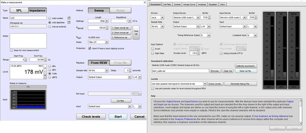
OK, I cleared calibration by clicking two buttons as on below picture:

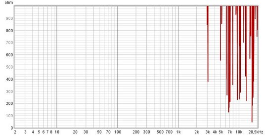
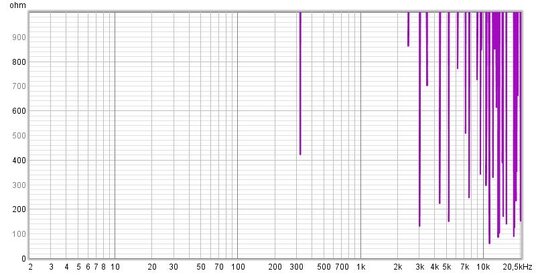
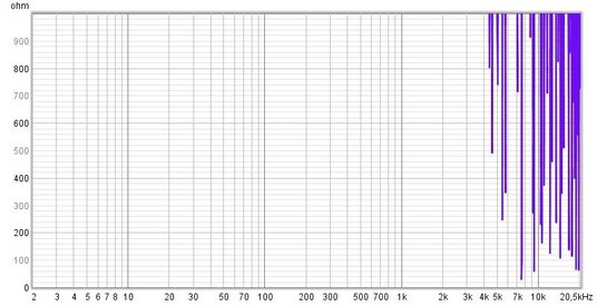
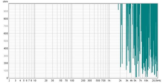
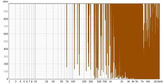
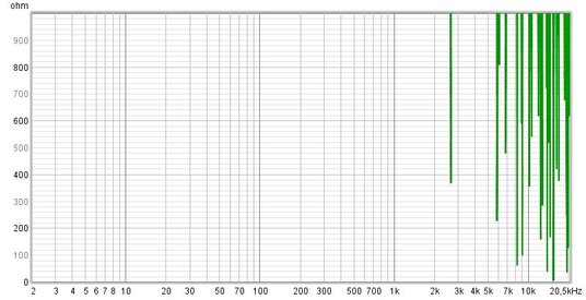
Next I measured impedance for correct input connection and next for swapped input. Results are presented in attachment. When I changed Rsense to 100ohm I obtained similar results. When I selected SPL measurements resulst seemed to be reasonable.
Next I measured impedance for correct input connection and next for swapped input. Results are presented in attachment. When I changed Rsense to 100ohm I obtained similar results. When I selected SPL measurements resulst seemed to be reasonable.
Attachments
-
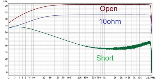 SPL.jpg65.1 KB · Views: 75
 -
 Swapped_input_impedance_10ohm.jpg58.7 KB · Views: 78
 -
 Swapped_input_impedance_shorted.jpg61.3 KB · Views: 72
 -
 Swapped_input_impedance_open.jpg59.4 KB · Views: 76
 -
 Impedance_10ohm.jpg58.8 KB · Views: 69
 -
 Impedance_short.jpg57.4 KB · Views: 60
 -
 Impedance_open.jpg59.9 KB · Views: 63

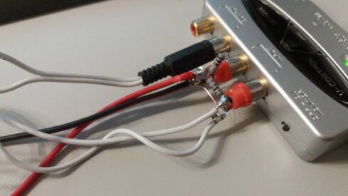
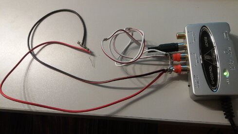
") . You asked me, that I should try to change input, from LEFT to RIGHT. Should I do it at the place marked at the picture (red arrow). If yes, it didn't bring any difference in my measurements. They looks similar. I can add that in my opinion proper output connection (red and black cable to speaker) shoud be connected to LEFT input. Then it is possible to observe differences in level on input level analuser (marked at the picture). If i connect it as instrcuction suggest, I see constant signal oninpul level analser for opened as well shorted measurement output. Hmm, it is strange... My cable connections are presented in attachments.
. You asked me, that I should try to change input, from LEFT to RIGHT. Should I do it at the place marked at the picture (red arrow). If yes, it didn't bring any difference in my measurements. They looks similar. I can add that in my opinion proper output connection (red and black cable to speaker) shoud be connected to LEFT input. Then it is possible to observe differences in level on input level analuser (marked at the picture). If i connect it as instrcuction suggest, I see constant signal oninpul level analser for opened as well shorted measurement output. Hmm, it is strange... My cable connections are presented in attachments.