John Mulcahy
REW Author
- Joined
- Apr 3, 2017
- Posts
- 9,393
Afraid not. Perhaps best to make sure a basic loopback measurement works normally before trying the impedance rig, if you haven't already checked that.


Follow along with the video below to see how to install our site as a web app on your home screen.
Note: This feature may not be available in some browsers.

")
Very good of her!My wife finally saw my frustration last night and pulled the plug, by which I mean she bought me the Dayton DATS box.
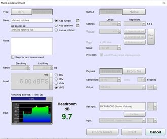
Sounds broken.I can say that on the external card, when there are no signal inputs, the level is at about -32dB, which I find very suspicious.
Can you explain what you mean by that? Why should there only be input on the L channel?Reason I though there was a problem is that the scope only had input on L channel, but I know realise that's by design
The file you attached contains one impedance measurement and nothing else.I've attached some REW measurements to see if they enable anyone to give any insights as to what I'm doing wrong. There are 2 loopback calibrations for the 2 soundcards followed by the impedance rig calibration process.
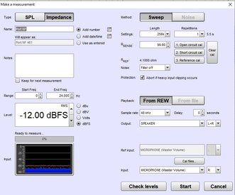
I see your screen grab of the measurement lists the "Microphone" as the input. Did you try to select "line in" input?I have the impedance rig driven by the headphone output of the UCA222 (or 202) and the output of the rig connected to the L/R line inputs.
Late arrival...I'm using this external card from Amazon: https://smile.amazon.com/gp/product/B076PC4VV4
Thanks, I changed it to the only other option on input "Default Input", same behavior both on L or R input channelI see your screen grab of the measurement lists the "Microphone" as the input. Did you try to select "line in" input?
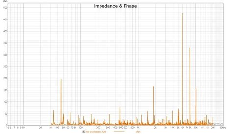
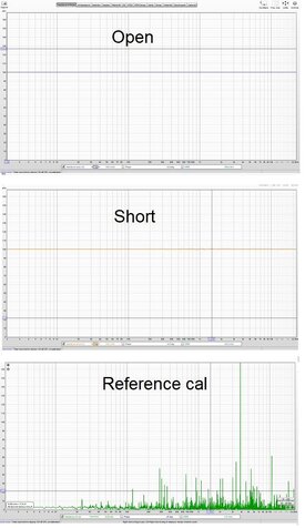
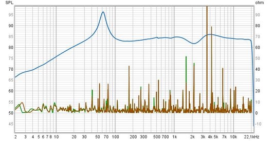
This is the same behavior I've been getting posted above. I'm afraid to say I couldn't resolve it and followed the thread initiator and bought a DATS box. It works fine with REW.Hello everyone. I encountered the same problem when measuring impedance. At the beginning, I used a built-in sound card. Unfortunately, no positive effects. Then I used the UCA202 card, the results were the same - bad. The problem is that after calibrating the "reference cal" instead of getting a straight 3ohm resistance line (I used such resistor), I get a very skewed graph that does not correspond to reality. I've been sitting on it for the third night and can't get it over with. Sample charts during calibration are presented below. I combined with levels, changed channels, mounted the measuring jig twice - with no results. I am also wondering why after short circuit calibration I get the result which is a straight line of 100ohm. I am using version 5.20.
I will be grateful for your help.
Yes. Have you tried clearing the calibration and measuring without it?Are you sure that v5.20 works correctly in terms of impedance measurement with the jig suggested in the manual?