Crazy results using Cable or Mic attached to sound card

Elmojo

New Member
Thread Starter
Joined
Aug 30, 2020
Messages
19
Hi all,
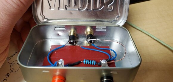
I'm trying to use REW to characterize speaker drivers, using the cable and method described in this video
(
), with follow up for the new Beta in this video
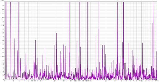
I think I have everything built and configured (mostly) correctly, but I'm getting crazy output graphs when I run measurements.
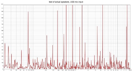
I get similar results on both my desktop PC, with an Audigy RX sound card, and my laptop, with built-in sound.
I'm running Beta 60 on both machines.
The first attached graphic is attempting to take free air measurements of a small driver on my desk, using the cable. The 2nd image is of my desktop speaker setup, recorded via my USB desktop mic (not calibrated I know, just trying to troubleshoot).
Any idea what I'm doing wrong?
I can post images of settings or anything you think will help pinpoint were I've gone astray.
Thanks in advance for any advice. I can't wait to dig into this software, it looks like so much fun! ;)

Edit: Yikes! I didn't expect it to embed the videos, sorry about that! I wouldn't let me link them, since it looked like spam I guess?
 

Attachments

  • REW_first graph.jpg
    REW_first graph.jpg
    254.3 KB · Views: 32
  • REW_speakers_USBmic.jpg
    REW_speakers_USBmic.jpg
    232 KB · Views: 32

EarlK

Member
Joined
May 22, 2017
Messages
221
Clearly ( looking at those graphs ) something has gone wrong.

Either the directions you followed are bunk ( No, I didn't bother to check the videos since they're not sanctioned here as far as I know ) or you weren't able follow along with those particular directions ( it doesn't really matter which ) .

Anyways; try a separate set of directions ( and then try again ).

Download the LIMP Tutorial[/url] and use it for it's in depth guidance and back-grounding ( even though it for a different program called LIMP all the basics are the same ) .

Good Luck!
:)
 
Last edited:

Elmojo

New Member
Thread Starter
Joined
Aug 30, 2020
Messages
19
Oh man, I think I may be in a bit over my head here.
I always thought I was a fairly smart cookie, able to figure things out if I put my mind to it, but this stuff is just cooking my brain.
I looked over the first part of that tutorial (thanks for the link EarlK!), but it's got too much theory and math for me to follow.
I guess I'm more of a visual learner than I thought. :)
I will say that the circuit looks very similar to the cable I built.
I have a 92.8ohm resister built into my cable (2 47-ohm in series, all I had on hand), which I assume is plenty close to the standard 100-ohm specified.
This is a measured rating, using my DMM, and corrected for the resistance of my leads (1.3ohm).
I had already thought about the usefulness of building this thing into a box rather than a dangly cable, which indeed is what's mentioned in the tutorial document.
I have a laser cutter, so the box won't be a problem.
I'm just not sure that my issue is related to the hardware itself. I was hoping I could get some help with the setup for REW, as far as what things should be set for, proper first steps, etc...
I read the getting started guide online, but it seems to jump around a bit, plus it appears to be for an older version.
 

Elmojo

New Member
Thread Starter
Joined
Aug 30, 2020
Messages
19
So I downloaded and read that LIMP tutorial document. I understood about 10% of it I think. ;)
While it was interesting, and I did pick up a few points that I plan to implement, should I ever get this rig up and running, I'm not totally getting what I need to do differently.
That guide is for ARTA/LIMP...something. I'm using REW. They do seem to be similar software, though.
I'd love to build that sweet ARTA measurement box, but that's far beyond my abilities at this point. Plus, I priced the parts, and I could pretty much just buy a Dayton DATS v3 and be done with it for what the box would cost. lol
Is anyone aware of a photo build guide or video tutorial that explains the hardware and software side of building the test rig for REW?
 

John Mulcahy

REW Author
Joined
Apr 3, 2017
Messages
7,212
Your measurements are just noise, so you probably have something wrong in the wiring connections. Make sure the ground is connected properly as shown in the diagram and that you don't have the left and right inputs swapped.

Getting good TS parameter data needs a stable mechanical mounting for the driver, an accurate scale for measuring the added masses to preferably 0.01 g accuracy and a lot of care when adding and removing masses from the cone.

34791
 

Elmojo

New Member
Thread Starter
Joined
Aug 30, 2020
Messages
19
Thanks John, that helps.
What do the ovals in the diagram above represent? They don't seem to be joints....
I was researching more last night, and ran across these images:
TSbox1.jpg TSbox2.jpg

Do they appear to be correct for building the circuit? As I said, I'm a visual learner, so if that first photo looks correct, I can build from that pretty easily.
I like the idea of having it in a box with jacks also, but I would use 3.5mm jacks instead of RCA, to avoid having to convert back and forth with adapters. Would this cause any issues?
 

John Mulcahy

REW Author
Joined
Apr 3, 2017
Messages
7,212
The ovals are the ground rings of the connectors. Those images look fine. Make sure the output channel selected in REW is the one connected to the resistor.
 

Elmojo

New Member
Thread Starter
Joined
Aug 30, 2020
Messages
19
Ah! Grounding, thanks.
I appreciate the feedback John.
I have a 5-ohm, 5W resistor on hand. Will that work, or do I need to buy something else?
I've seen somewhat conflicting info on whether that resister needs to be higher wattage-capable, and if the specific rating is super important or not...
 

John Mulcahy

REW Author
Joined
Apr 3, 2017
Messages
7,212
A value that low would need to be driven by a power amplifier, and would usually need attenuators at the soundcard inputs to remove the risk of destroying the soundcard if the voltages got too high. If you plan to drive with a soundcard/headphone output you will need to keep the resistor above 50 ohms or so.
 

Elmojo

New Member
Thread Starter
Joined
Aug 30, 2020
Messages
19
Gotcha, thanks.
Is it necessary to have a resistor capable of higher power handling, or is a typical 1/4 or 1/2-watt resistor fine?
 

John Mulcahy

REW Author
Joined
Apr 3, 2017
Messages
7,212
Power handling isn't an issue when driving typical resistor values with a soundcard, the voltages are too low and the resistance too high to dissipate any significant power.
 

Elmojo

New Member
Thread Starter
Joined
Aug 30, 2020
Messages
19
Cool. Thanks so much for your help John.
I haven't dug in enough to know much yet, but your software looks amazing!
 

Elmojo

New Member
Thread Starter
Joined
Aug 30, 2020
Messages
19
Ok folks, I'm completely baffled here. Someone PLEASE tell me what I'm doing wrong.
I've started over and built a new circuit from the images posted above. You can see what it looks like in the images below.
I've read through the help guide for REW, and I think I'm doing the calibration steps correctly.
I run REW, and step through each cal step, after setting my channels and such in the preferences.
I get what seems to be good, reasonable outputs on the soundcard calibration (from preferences screen), open circuit cal, and short circuit cal.
However, when I run the 3rd step, the reference resister cal, things just go haywire.
I don't understand what I'm doing wrong, and it's maddening. I've rebuilt this thing several times to correct little issues, but obviously something is still wrong. I don't know if it's in the physical circuit, the settings for the sound card in Windows, the prefs in REW, or something else. Help? 20200910_160041 (Large).jpg 20200910_160126 (Large).jpg 20200910_160114 (Large).jpg opencircuit_cal.jpg shortcircuit_cal.jpg ref_resist_cal.jpg soundcard_cal.jpg
 

John Mulcahy

REW Author
Joined
Apr 3, 2017
Messages
7,212
Input channels swapped I'd say, can change the input channel selection in REW. The short circuit cal is showing 100 ohm, rather than something close to zero, which is typical of swapped input channels.
 

Elmojo

New Member
Thread Starter
Joined
Aug 30, 2020
Messages
19
You know, I thought that also, since you mentioned it before. However, I've tried it both ways and get pretty much the same results.
Does the circuit itself look correct, as best as you can tell from the images?
 

jtalden

Senior Member
Joined
May 22, 2017
Messages
887
Location
Arizona, USA
More  
Preamp, Processor or Receiver
Marantz AV7705 Pre/Pro
Main Amp
VTV 6 chnl NC252MP P-amp x 2
Additional Amp
Behringer DCX2496 x 2
Universal / Blu-ray / CD Player
OPPO BDP-103 Universal Player
Front Speakers
DIY SEAS H1456/H1212 Spkr x 5
Subwoofers
DIY JBL 2235H 15" SW x 2
Video Display Device
JVC DLA-X790R
Screen
Da-Lite Da-Snap 39105V - 92"
I'm no expert on impedance testing, but a couple of connections don't look right.
  • The soundcard line input should be used (not the mic input) so the white cable needs to be moved over to that input on the soundcard.
  • It appears to me the green wire connection in the mint box has the soundcard output connected to the left channel. It should be connected to the right channel. Move the wire over to the right channel pin.
REW then should use the right channel as the measurement channel.
I am assuming that the pinout order as shown in the picture are; right/ground/left for both chassis jacks. It is hard to tell for sure from the picture.
 

Elmojo

New Member
Thread Starter
Joined
Aug 30, 2020
Messages
19
Good catch on that mis-soldered pin! I had found and fixed that after taking the photos, and forgot to mention it, sorry about that!
I've tried using the LINE-IN jack, but the input levels are too low to use. REW tells me that I need to do something to increase the level. Using the headphone jack (suggested in other guides) seems to meet that criterium.
I swear I'm not usually this dense, but this thing is absolutely kicking my butt! :/
Here's another photo that might be a better angle.
 

Attachments

  • 20200910_181411 (Large).jpg
    20200910_181411 (Large).jpg
    156.2 KB · Views: 34

John Mulcahy

REW Author
Joined
Apr 3, 2017
Messages
7,212
Headphone jack is for output. Line in is for input. Mic in likely has restricted bandwidth and excess gain, use the line in and find where its level control is.
 

Elmojo

New Member
Thread Starter
Joined
Aug 30, 2020
Messages
19
I'm sorry, I misspoke. There is no headphone jack on this setup. I'm using a USB external sound card, as shown in the 2nd photo attached to Post #13.
If I switch to using LINE in, and run the soundcard calibration, I can only get reasonable results if I plug one side of the loopback in only halfway on one jack. If I fully insert both jacks into the LINE IN and FRONT OUT jacks as you'd expect, then the level of the IN channel is in the +2.8dB area. This is with LINE set at about 50% in Windows. If I drop the slider for the line in control in Windows to about 40, it drops right down to -32.1dB, which seems to be "off". There's no middle ground. 40% is off, 41% is wide open. If I go above about 50%, the value in REW actually begins to drop. at 100%, it's at -0.2dB.
However, if I plug one side of the loopback in only halfway (one channel I guess), then the slider in Windows does exactly what you'd expect it to, and I can balance the levels at about 38% on the LINE IN, and complete the calibration with something that looks like an actual graph.

BUT....once that's all done, if I go back and try to take an actual measurement, with the connections back like you'd think they should be, things go waywire again. I keep getting messages about the reference level being too low, but I don't know which one that is, or what to do about it.

None of this makes any sense to me. Anyone see a pattern or cause, other than me being an idiot? lol
 

John Mulcahy

REW Author
Joined
Apr 3, 2017
Messages
7,212
That behaviour sounds like the result of monitoring being active, i.e. the line in is being mixed back into the front out. That can happen if "Listen t this device" is selected in the Windows audio properties for the input or if the interface has some monitoring control or mixer which is active.
 

Elmojo

New Member
Thread Starter
Joined
Aug 30, 2020
Messages
19
I checked, and there's no "listen" box checked for the line in or mic input on this unit. I did notice that the level set in one place doesn't seem to mach that in another, which leads me to believe that it's not giving me the full into about the inputs and outputs, but I have no idea if that's a Windows 10 thing, or something to do with the sound card itself, or how to go about checking that.
I plan to test this rig on my laptop with the built-in sound card to see if I get similar or totally different results.
 

Elmojo

New Member
Thread Starter
Joined
Aug 30, 2020
Messages
19
So I checked on my laptop, with a totally different sound card, and got similar crazy results.
One thing occurs to me... Do the cables going between the sound card itself and the measure box need to be anything other than typical "aux cables"?
I feel like something must be wired wrong somewhere, I just can't fathom where it can be.
I think if I have time tomorrow, I'm gonna build another circuit from scratch, not in a box, just open rats nest wiring, and see if makes any difference.
 

Elmojo

New Member
Thread Starter
Joined
Aug 30, 2020
Messages
19
I absolutely give up. I went back and built a brand new cable, being extra careful of all my connections.
I was able to get the calibration to (maybe) work on my laptop, but that's it. Everything else has given all sorts of crazy output, and errors that I can't make sense of. I've searched the help files, and googled most of the morning, and can't find anything that seems to address what I'm seeing. For example, the 'check levels' screen shows that everything looks good, but when I try a measurement, it says the Reference In is too low, and fails.
At this point, I've tried it on 2 machines, with 3 different sound cards, and not once have I gotten anything that resembles expected output.
Apparently I'm not going to be able to figure this out, and should just move on to some other hobby. :(
I've spent so many hours, and quite a bit of money in parts, that I could have just bought a DATS v3 and been done with it long ago.
I'm sure this is great software, I just wish I was smart enough to learn it.
 

John Mulcahy

REW Author
Joined
Apr 3, 2017
Messages
7,212
The reference input is the one the output is directly connected to, so it would be odd for it to be low.
 

Elmojo

New Member
Thread Starter
Joined
Aug 30, 2020
Messages
19
I agree. It's just one of the things that don't make sense to me.
It seems that every time I hook it up, I get slightly different results, but never anything usable.
Are there any known bugs in Beta 60 that could cause this type of erratic behavior?
 
Top Bottom