


-
AUDIO VIDEO PROCESSING, SETUP & ENVIRONMENTOfficial REW (Room EQ Wizard) Support Forum Audiolense User Forum Calibration Equipment Auto-EQ Platforms / Immersive Audio Codecs Video Display Technologies / Calibration AV System Setup and Support Listening Room / Home Theater Build Projects Room Acoustics and Treatments AV Showcase Movies / Music / TV / Streaming
-
AUDIO VIDEO DISCUSSION / EQUIPMENTHome Theater / Audio and Video - Misc Topics Essence For Hi Res Audio AV Equipment Advice and Pricing Awesome Deals and Budget AV Equipment AV Receivers / Processors / Amps UHD / Blu-ray / CD Players / Streaming Devices Two Channel Hi-Fi Equipment DIY Audio Projects Computer Systems - HTPC / Gaming HD and UHD Flat Screen Displays Projectors and Projection Screens AV Accessories Buy - Sell - Trade
Navigation
Install the app
How to install the app on iOS
Follow along with the video below to see how to install our site as a web app on your home screen.
Note: This feature may not be available in some browsers.
More options
You are using an out of date browser. It may not display this or other websites correctly.
You should upgrade or use an alternative browser.
You should upgrade or use an alternative browser.
Capacitors, inductors and resistors measurements
- Thread starter Cristianolo
- Start date

Following.
Attachments
-
225.mdat1.9 MB · Views: 112
-
333.mdat1.9 MB · Views: 127
-
334.mdat1.9 MB · Views: 140
-
335.mdat1.9 MB · Views: 130
-
473.mdat1.9 MB · Views: 101
-
474.mdat1.9 MB · Views: 120
-
475.mdat1.9 MB · Views: 116
-
563.mdat1.9 MB · Views: 115
-
564.mdat1.9 MB · Views: 135
-
683.mdat1.9 MB · Views: 121
-
684.mdat1.9 MB · Views: 142
-
823.mdat1.9 MB · Views: 119
John Mulcahy
REW Author
- Joined
- Apr 3, 2017
- Posts
- 9,390
Very useful Oliver, thanks. The measured DC R values all seem to be about 1.2 ohm higher than the specified values.
Hi John,
just for more info, my system has been calibrated before the measurements.
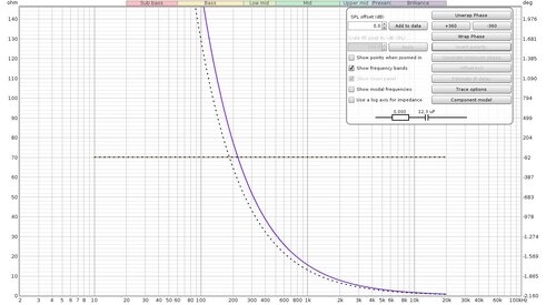
Attached the result for a 4.7 Ω resistor.
Regarding the previous measures, below 18uH the "component model" button doesn't become not active.
If you want me to perform other measures just let me know.
just for more info, my system has been calibrated before the measurements.
Attached the result for a 4.7 Ω resistor.
Regarding the previous measures, below 18uH the "component model" button doesn't become not active.
If you want me to perform other measures just let me know.
Attachments
John Mulcahy
REW Author
- Joined
- Apr 3, 2017
- Posts
- 9,390
I don't doubt themeasurements, just thought it interesting that the components all seemed to have an additional resistive component beyond the specified value.just for more info, my system has been calibrated before the measurements.
Attached the result for a 4.7 Ω resistor.
Yes, the phase for the smaller values wasn't reaching the threshold at the check frequency, I have adjusted that.Regarding the previous measures, below 18uH the "component model" button doesn't become not active.
Antonio Di Motta
Member
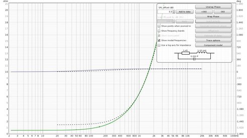
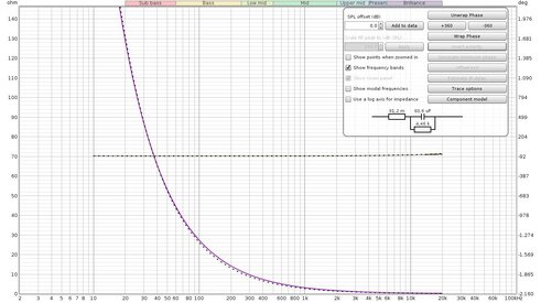
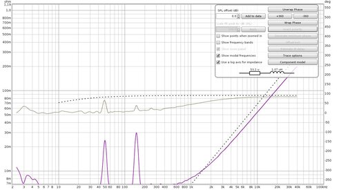
Finally I managed to test with the latest version of REW, I measured a 1mH inductance with a series resistance of 0.55 ohms. I noticed that by positioning the cursor on the curve the effective value of the inductance varies from 1.02mH to 1.03mH while the series resistance is at 10Hz and 0.557 ohm in line with what is declared by the component. On the model of the component the inductive value is approximate to the value of 1mH but the series resistance is much higher 1.45 ohm instead of 0.557ohm reported when I position the cursor.
Is there something wrong or wrong with interpreting the component model function?
Is there something wrong or wrong with interpreting the component model function?
Attachments
John Mulcahy
REW Author
- Joined
- Apr 3, 2017
- Posts
- 9,390
There is a better model in the next build, I will release it shortly.
Jimmy Venema
Registered
- Joined
- Apr 25, 2019
- Posts
- 17
I like the new component model option. But in version 50 the capacitors model seemed ok, but the serie resistance of inductor was way too high. With version 51 the inductance seems oke, but now the capacitors seems way off, no resistance en the fit is not ok.

John Mulcahy
REW Author
- Joined
- Apr 3, 2017
- Posts
- 9,390
Please attach mdat files rather than images.
Jimmy Venema
Registered
- Joined
- Apr 25, 2019
- Posts
- 17
Here a zip file of the mdat file with one inductor and a few capacitors. A 7z compressed file was not allowed to upload. Perhaps an idea to allow that, since the file size was 11 MB vs 19.5 MB. It is not that 7z is uncommon, in most places it replaced zip years ago.
Attachments
Jimmy Venema
Registered
- Joined
- Apr 25, 2019
- Posts
- 17
I've just tested with the 52 version and the capacitors are still off as in the 51 version, while they were ok in the 50 version.
John Mulcahy
REW Author
- Joined
- Apr 3, 2017
- Posts
- 9,390
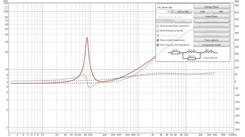
The underlying problem is the accuracy of results after calibration. You may have noticed that the real part of your capacitor measurements is zero over much of the range, whilst it should never be less than the series resistance component. The curve also deviates from the expected response at the lowest frequencies. I can accommodate that by only fitting capacitors over the range from 100 Hz upwards and using the last part of the response to establish bounds for the series resistance element, that gives the results below for your 390 nF measurement. You can see the response deviation below about 30 Hz.I've just tested with the 52 version and the capacitors are still off as in the 51 version, while they were ok in the 50 version.

I was being a bit unrealistic in my expectations of measurement accuracy, the setup I am using (with an ADI-2 Fs Pro) is a lot more accurate than I expected it to be but that is likely an outlier. By way of example, even a 10 nF capacitor is accurately captured to the point the impedance gets to about 3Mohm, I had to increase the precision of the calibration file entries to fully reproduce the equipment accuracy (that change will be in the next build, along with the capacitor match changes).
Jimmy Venema
Registered
- Joined
- Apr 25, 2019
- Posts
- 17
A 390nF capacitor is normally used a bit higher in frequency then 30 Hz ;-). In fact in my case it was only used in parallel with an another higher valued capacitor to get at a needed value that wasn't available in the normal E series. At the boundaries there will always be deviations. But I guess a lot of people are going to use this feature to verify their components for either a passive or active filter. So they are more interested at what the value is at their target crossover point than what the behaviour at the extremes is. Perhaps give an option to give a center frequency en over how many octaves the best fit should work. I guess the value 3 octaves away from the target working point is less important.
But anyway this is a very nice feature and the accuracy quite impressive. I used it before the model option and I moved the cursor around the crossover area and then read the value at the left bottom corner.
But anyway this is a very nice feature and the accuracy quite impressive. I used it before the model option and I moved the cursor around the crossover area and then read the value at the left bottom corner.
John Mulcahy
REW Author
- Joined
- Apr 3, 2017
- Posts
- 9,390
Sure, but just to be clear for anyone reading, it is not the capacitor that is deviating from expected behaviour, it is the impedance measurement.A 390nF capacitor is normally used a bit higher in frequency then 30 Hz
Jimmy Venema
Registered
- Joined
- Apr 25, 2019
- Posts
- 17
Sure the deviations for a capacitor even small ones are more to the higher end of the frequency range, because of the inevitabel inductance. So indeed the deviation at low frequencies is in the measurement of the impedance. The measurement rig has also coupling capacitors etc, so that would influence measurements at the boundary of the rig.Sure, but just to be clear for anyone reading, it is not the capacitor that is deviating from expected behaviour, it is the impedance measurement.
My point is that a designer is interested in the component value in the frequency range were it should do its filter function. Deviations from that value outside that area are not that relevant.
Antonio Di Motta
Member
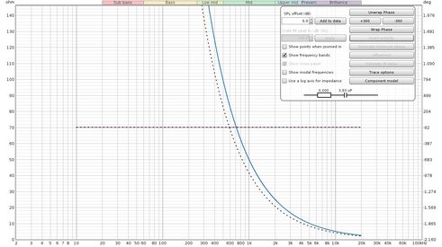
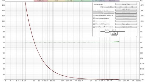
John, I made many measurements to verify the accuracy of the values detected by the Component model function and I must say that it behaves quite well, even if sometimes it makes mistakes between the values that are detected by positioning the cursor on the graph and those calculated with said function . For example, I measured a 10uF non-electrolytic capacitor with 5% accuracy and the value calculated by the function was 12.3uF while the cursor detects 10.2uF. I also noticed that almost always the values of the series resistance of the paper capacitors or polyester is equal to 0.000 ohms, perhaps it is particularly generous in the evaluation of the series resistance.
Again for capacities, I noticed that under the values of 0.2uF the component model does not activate while on the cursor it continues to detect much smaller values, for example I measured a capacity of 12.1nF 0.625%.
As for the inductances it doesn't seem to have these limits, I measured an inductance of 1uH without particular problems.
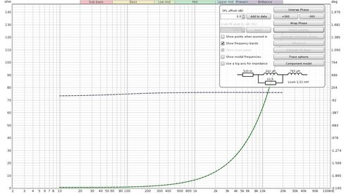
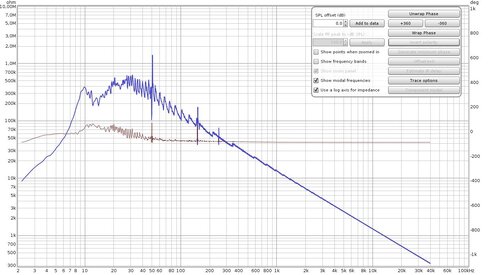
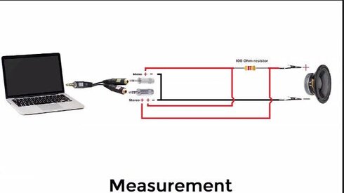
I also carried out a test with a speaker and the model considers only the inductance of the moving coil excluding the values of the circuit oscillating on the cone's resonance frequency. This choice seems to me absolutely correct. I attach the tests I have carried out for any checks.
Thanks for the attention
Again for capacities, I noticed that under the values of 0.2uF the component model does not activate while on the cursor it continues to detect much smaller values, for example I measured a capacity of 12.1nF 0.625%.
As for the inductances it doesn't seem to have these limits, I measured an inductance of 1uH without particular problems.
I also carried out a test with a speaker and the model considers only the inductance of the moving coil excluding the values of the circuit oscillating on the cone's resonance frequency. This choice seems to me absolutely correct. I attach the tests I have carried out for any checks.
Thanks for the attention
Attachments
-
 Induttanza_1mH_0.55ohm.jpg169.5 KB · Views: 96
 -
Induttance 1mH 0.55ohm mag 19.mdat901.6 KB · Views: 112
-
 Capacita 3.3uF.jpg169.8 KB · Views: 91
 -
Capacita 3.3uF mag 19.mdat901.6 KB · Views: 93
-
 Capacita 4.7uF.jpg167.2 KB · Views: 87
 -
Capacita 4.7uF mag 19.mdat901.6 KB · Views: 106
-
 Capacita 10uF.jpg170.6 KB · Views: 99
 -
Capacita 10uF mag 19.mdat901.6 KB · Views: 102
-
Capacita 47uF Elet._not_pol.mag 19.mdat901.7 KB · Views: 115
-
 Capacita 47uF elet.jpg169.7 KB · Views: 93
 -
 Capacita 100uF elet.jpg169 KB · Views: 82
 -
Capacita 100uF Elet._not_pol.mag 19.mdat901.7 KB · Views: 100
-
 Induttanza_1.5mH_nucleo_lamellare.jpg169 KB · Views: 78
 -
Induttance 1.5mH_nucleo_lamellare mag 19.mdat901.6 KB · Views: 85
-
 Induttanza_1uH.jpg135.4 KB · Views: 90
 -
Induttanza 1uH mag 21.mdat2.5 MB · Views: 118
-
 Altoparlante_20Cm.jpg131.3 KB · Views: 93
 -
Altoparlante 20cm mag 21.mdat1.7 MB · Views: 120
-
 Capacita 12100pF_di precisione.jpg156.7 KB · Views: 91
 -
Capacita 12100pF di precisione mag 21.mdat1.7 MB · Views: 100
Antonio Di Motta
Member
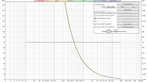
Last measurement made of 2670pF capacitor with 0.625% accuracy measured with the cursor a positioned at 40Khz with a value of 2640pF 2.64nF. Excellent precision given the low capacity value.
Attachments
John Mulcahy
REW Author
- Joined
- Apr 3, 2017
- Posts
- 9,390
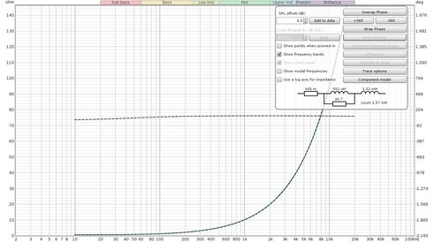
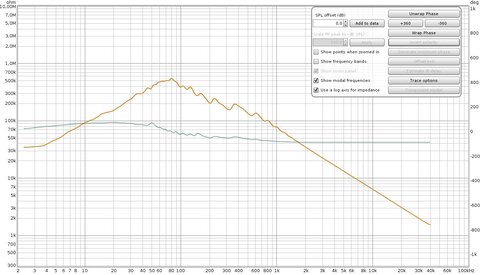
The calibration file resolution increase in the next build will address the sawtooth impedance traces you are getting at high impedances, which should give better measurement results. In the meantime here is how the new capacitor model does with those caps, bearing in mind the lowest values should be better after remeasuring with the next version:

John Mulcahy
REW Author
- Joined
- Apr 3, 2017
- Posts
- 9,390
Image looks OK. Impedance measurement.


Popular tags
20th century fox
4k blu-ray
4k uhd
4k ultrahd
action
adventure
animated
animation
bass
blu-ray
calibration
comedy
comics
denon
dirac
dirac live
disney
dolby atmos
drama
fantasy
hdmi 2.1
home theater
horror
kaleidescape
klipsch
lionsgate
marantz
movies
onkyo
paramount
pioneer
rew
romance
sci-fi
scream factory
shout factory
sony
stormaudio
subwoofer
svs
terror
thriller
uhd
ultrahd
ultrahd 4k
universal
value electronics
warner
warner brothers
well go usa