5.20.5 impedance measurement

trobbins

Member
VIP Supporter
Thread Starter
Joined
Nov 26, 2017
Messages
121
Location
Australia
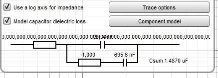
John, thanks so much for changing the displayed values to 4 digits - very impressive. I have had a little time to make a batch of capacitor impedance measurements - very repeatable values when the cursor selected frequency is in the goldilocks range (not too low, not too high). On one measurement I noted that one value in the component model window has a bug - attached file - and overlays another component value - perhaps due to the model complexity used. All other measurements have been fine and shown a simple R-C model.

For the polystyrene dielectric capacitors I have been measuring, using a cursor selected frequency and the cap value in the bottom left appears to be valid, whereas the model component value of capacitance shows some minor difference that I can't seem to align with any spot value in the 100Hz to 20kHz range.

I've tried twice to load the mdat (60Meg) but it doesn't seem to show in post one it reaches 100% upload (?)
 
Last edited:

John Mulcahy

REW Author
Joined
Apr 3, 2017
Messages
7,342
There's a 50 MB limit on uploads so probably need to split the measurements to upload them. Can you post a screenshot of the component model overlap?
 

trobbins

Member
VIP Supporter
Thread Starter
Joined
Nov 26, 2017
Messages
121
Location
Australia
Ta. Re did test with lower length setting (same bug presentation). So file attached for that, as well as screengrab for simple viewing.
 

Attachments

  • 900nF model.mdat
    7.5 MB · Views: 10
  • Screengrab.PNG
    Screengrab.PNG
    4 KB · Views: 27

John Mulcahy

REW Author
Joined
Apr 3, 2017
Messages
7,342
Note: to avoid that bug end the cap measurement below 40 kHz. The model fit only uses data up to 20 kHz.
 

trobbins

Member
VIP Supporter
Thread Starter
Joined
Nov 26, 2017
Messages
121
Location
Australia
Thanks so much John - this is an amazingly simple but powerful tool, and the enhanced resolution indicates how consistent the measurement values can be between measurements (I am seeing sample to sample spread of much less than 0.1% for capacitance), which bodes well for being able to show absolute accuracy down to circa 0.1% once I can get an independent measurement scheme confirmed.

Btw, how is frequency determined by REW - from a mains frequency derived basis?
 

John Mulcahy

REW Author
Joined
Apr 3, 2017
Messages
7,342
The sample rate setting tells REW all it needs to know for frequencies, as long as the audio data it gets is at the sample rate it claims to be all is well.
 

trobbins

Member
VIP Supporter
Thread Starter
Joined
Nov 26, 2017
Messages
121
Location
Australia
I just checked the frequency accuracy of the master crystal oscillator in my EMU0404USB and a 10kHz sinewave input (digitally derived from HP3325A with external GPSDO reference that is within 1ppb of 10MHz), displays as 10,000.11Hz. No change for different FFT lengths and ASIO sampling rates and JAVA. Commanding 9,999.9Hz causes a display of 10,000.01Hz, and commanding 50kHz displays 50,000.58Hz, so soundcard frequency is circa 0.0011% tolerance slow, which to me validates frequency accuracy. :)
 

sm52

Member
Joined
Mar 14, 2019
Messages
892

trobbins

Question about measuring distortion in the RTA window. You once used this phrase in a conversation - 'measuring RTA with a loopback'. Is the loopback always needed for these measurements or for some special cases?
 

trobbins

Member
VIP Supporter
Thread Starter
Joined
Nov 26, 2017
Messages
121
Location
Australia
sm52, I'm not sure I appreciate your query. Distortion measurement is part of an external device RTA measurement (eg. a frequency sweep of an amp). As a baseline, the external device is removed and just a simple 'loopback' connection is made - as a way of confirming the measurement system's performance. The external device is then inserted in the 'loop' and REW measures the new response, which can then be compared to the baseline.
 

sm52

Member
Joined
Mar 14, 2019
Messages
892
A friend of mine measures the distortion and frequency response of a tube preamp. He states that the loop connection during these measurements is mandatory. I made a sound card calibration file a long time ago, and it is always used in REW. I measured my amplifier without loop connection. I got distortion in the RTA window when applying 1 kHz, I saw harmonics. Then I ran a sweep and got the frequency response. Then I had a question whether a loop connection is necessary during such measurements.
 

trobbins

Member
VIP Supporter
Thread Starter
Joined
Nov 26, 2017
Messages
121
Location
Australia
An REW measurement of say frequency response, or to make a calibration, does inherently include a 'loop' as the signal is generated by the soundcard, then exits the soundcard and is then returned to the soundcard input socket. A loopback test in its simplest form just connects the soundcard's output directly to its input - see graphic of a loopback attached below (from Mathworks.com site). Measurement of some external device effectively forms the same 'loop' but inserts the external device in the cabling between the soundcards output and its input.
 

Attachments

  • xxMeasuringLatency1.png
    xxMeasuringLatency1.png
    3.5 KB · Views: 8

trobbins

Member
VIP Supporter
Thread Starter
Joined
Nov 26, 2017
Messages
121
Location
Australia
Incorrect. That hand drawing shows a signal looping from the Focusrite Solo RCA (the soundcard output) to the amp input (device under test) to the 8 ohm dummy load, and then back to the Focusrite line input (the soundcard input).
 

sm52

Member
Joined
Mar 14, 2019
Messages
892
So that's what you mean by loop! I call it the measuring chain. And my original question was about a loop, which in REW is called Loopback, from the output of the sound card directly to the input of the sound card. Which is used when measuring the frequency response for synchronization. This means that to measure the distortion of the amplifier, as well as the frequency response of the amplifier, it is enough that hand-drawn circuit. Loopback is not required. Right?
 

trobbins

Member
VIP Supporter
Thread Starter
Joined
Nov 26, 2017
Messages
121
Location
Australia
sm52 - perhaps re-read post #10. A somewhat similar analogy is when making a resistance measurement with a multimeter - firstly short the probes to determine the 'zero' reading level, and then measure the unknown resistance.
 
Top Bottom