Nearfield EQ adjustments

Bengt Nilsson

Registered
Thread Starter
Joined
Aug 3, 2018
Posts
14
More  
Main Amp
Marantz PM 6004
Additional Amp
Musical Fidelity A1
Universal / Blu-ray / CD Player
N/A
Front Speakers
Fostex FX120 b/ SEAS A26RE4
Hi,

I am trying to adjust a speaker with a DSP EQ to have a flat low frequency SPL indoors.
I will not go into why at this point.
Is it possible to make a near field mic setup and apply a "mic calibration file" with the inverted (simulated) diffraction response?
This would of course work only up to the maximum near field frequency, same limitations as a merger software would require.
If it works, it would simplify a lot and avoid outdoor activities.
Or is it a crazy idea, to be directly passed in to the bin?

BN
 
You can just load the diffraction response and use arithmetic division or multiplication. But, for low frequency response, room boundaries usually dominate the response, baffle diffraction is only a small portion of the resulting acoustics so I'm not sure what the point would be to apply a nearfield EQ when you listen in the far field.
 
Last edited:
If you make a DSP crossover filter, it is in my view very important that the SPL of each driver is "following the filter." If not, you have absolutely no control of what is coming out. To do that, each driver should be driven by an EQ to have a "flat" SPL before the crossover applied. After that, the signal is passed into the crossover and the total SPL sum is more likely to conform to the desired crossover design. (In fact, in reality the EQ should be applied AFTER the crossover filter output, to secure the headroom if you will apply any positive PK adjustments in the frequency regions in the slope towards the stop band(s).)
And as you say, the room boundaries create real problems both in the listening experience and measurements, especially at low frequencies. You have to apply near field measurements if you want to work indoors, and then you lose the diffraction and baffle step behaviour.

I know how to work with diffraction response and arithmetic division. My question was about putting the diffraction response "inline" to the measurement process to save time and effort. This question is not yet answered. I guess I will simply try it out by myself and compare to the standard methods.
 
Last edited:
I just read your post again and I think I missed to comment.
I'm not sure what the point would be to apply a nearfield EQ when you listen in the far field.
This is exactly the point.
I want to transfer a NF measurement into a FF equivalent measurement by applying the diffraction response to it.
Does it make sense now?
 
It doesn't make sense to EQ a calculated far field response that doesn't include room effects which will dominate the response at low frequency. Just measure the speaker in-room and EQ directly from there.
 
Sounds a bit impractical. Move half a meter to the side and it will be different.;)
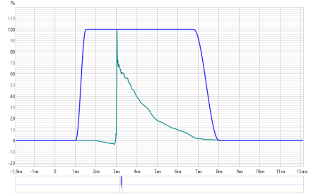
But the real issue is when you want to match a midrange driver to a woofer, it is good to have a fair idea of what is actually coming out at the crossover frequency. And this can be difficult at frequencies below the room measurement limit. The first reflexes are coming after around ≈3ms so you cannot measure FF reliably below 300Hz.
 
Sounds a bit impractical. Move half a meter to the side and it will be different.;)
That's why you take average of multiple locations of seating area, or use RTA average to capture a room response quickly.
.But the real issue is when you want to match a midrange driver to a woofer, it is good to have a fair idea of what is actually coming out at the crossover frequency. And this can be difficult at frequencies below the room measurement limit. The first reflexes are coming after around ≈3ms so you cannot measure FF reliably below 300Hz.
No longer talking about room EQ. If you want to measure for loudspeaker crossover design, I recommend combining REW with VituixCAD and following the great guide that exists for this task:
 
As I started this thread, I as never talking about room EQ, but I agree I was not so clear about my purpose, sorry.
Apples and pears...
I know this document, and I am using REW and VituixCad.
 
When you said "I am trying to adjust a speaker with a DSP EQ to have a flat low frequency SPL indoors." that's what implied room EQ to me.

Instruction on combining near field, far field, and diffraction in all detailed in the VituixCAD guide, so I guess I'm not understanding what part you're having trouble with?
 
Ok, I have a well established and documented inability to make myself understod in forums. Sorry about this.

I will try again.
I am working with an active 3-way speaker system driven by a DSP.
I am using 4th order Linkwitz-Riley filters where the electrical signal sum of LP and MP makes a flat frequency response, same for the MP and HP.
When these signals are fed to the drivers without any further adjustments, the SPL sum is no longer flat due to the driver properties, timing, baffle step and diffraction effects.
In order to make the crossover filter do its job properly, I am trying to apply EQ on the drivers, separately for LP and MP, to make the FF SPL flat in the crossover frequency region before the crossover filter is applied. The flatness of the unfiltered SPL should extend by at least an octave beyond the crossover frequency to make the crossover filter SPL blend well. I am using the term "follow the filter", meaning that the SPL of the LP and MP drivers measured at FF should match the level and slope of the Linkwitz-Riley filters in the frequency overlap region.
The room boundary effects are of course going on top of this, but that is a different story and may be compensated for later.
Again: The idea is apply EQ so the acoustic output from the drivers will blend in the same way as the electric signals would.
In order to adjust the EQ properly, it will be necessary to measure the driver FF output correctly.

The original question in this thread was if it would be a good idea to combine the simulated diffraction response and microphone calibration data into the same file to save some time and effort since it will be necessary to do NF measurements to cover the full frequency range.
 
Ok, no problem. You are using a "textbook filter" and it doesn't provide a textbook acoustic response, this is expected. I think you are over-complicating things though.

This is what I would do:
  1. Complete measurement process detailed in VituixCAD guide to create the full-space response for your drivers.
  2. Load driver responses to VituixCAD, and apply the text book filter to the drivers.
  3. Apply any other external EQ required upstream.
  4. Don't be surprised if power & DI is not as expected, textbook filter may not align phase of drivers well at the crossover frequency. A properly designed crossover filter would be preferred over the textbook filter.
Crossover schematic can look like this:
1757080872750.png


To confirm LR24 filter in VituixCAD matches your textbook filter, you may want to measure the driver with the filter in place, and compare to VituixCAD simulation with high pass / low pass filter and adjust so they match. Assuming an active LR24 filter, you could loop its output back to your audio interface and measure it's transfer function, then just adjust the filter in VituixCAD to match.

Alternatively, if the LR24 crossover is a fixed non-adjustable filter, you may just measure your drivers with the crossover in place and EQ from there. This may provide more reliable results.
 
Last edited:
Ok, now you have lost me in your terminology. What is a textbook filter?
 
Textbook is exactly that, a filter response that follows the textbook definition for LR, BW, etc. It assumes input is flat response, for loudspeakers a textbook filter provides no consideration for the non-linear acoustic magnitude response, so while the electrical filter follows LR24 transfer function exactly, acoustic response will be far from it.

Reality is that if you want a LR24 acoustic output, the electrical filter needs to diverge significantly from the textbook definition a far as an electrical transfer function goes.

To make sure I'm not making some poor assumptions, what is the physical hardware you are using to provide the "4th order LR filter" and the EQ?
 
"In theory there is no difference between theory and practice. In practice there is". -Yogi Berra-
 
The physical hardware is an Analog Devices ADSP-SC589 EZ board, with a SigmaStudio design project. The DSP has XMOS USB IS2 input, 6 channels of I2S output, connected to a "motherboard" with three DAC boards from Audiophonics (https://www.audiophonics.fr/en/dac-...spdif-pcm-dsd-usb-c-power-supply-p-12795.html). DSP output is connected to three 25W class A stereo power amps. LP driver is a SEAS 10-inch A26RE4 H1411-08 in a 70 liter ceramic enclosure for Q=0.71, MP driver is a Scan-Speak 4-inch 15W/4424G00, HP driver is a SB21RDC-C000-4 ring radiator.
The SigmaStudio project is a phase linear crossover filter, implemented as a 3-way subtraction filter. This behaves very similar to a regular FIR filter, except that it requires only 10-15% of the MIPS load of a FIR filter. A 3-way LR24 FIR filter would not be possible with my DSP hardware, I have tried and it failed due to overload at 192k sampling rate.
The reason I am working with this configuration is that I want implement a speaker system with a time coherent step response.
Below is an outdoor mic REW measurement of the step response of LP, MP, HP, and ALL (total system) with a 15ms time window.
The wigglyness of the SPL graph is because a time window long enough to cover 30-20kHz will include some ground reflections.
LP.png
MP.png
HP.png
ALL.png
at 1m distance.
SPL.png
 
Last edited:
The reason I am working with this configuration is that I want implement a speaker system with a time coherent step response.
Does your equipment have the ability to set delays for individual channels? For a mid-range driver, for a high-frequency driver?
 
Yes, absolutely. This is a very important design parameter.
 
Could you show on the graphs what causes your dissatisfaction when applying the available filters in the range of low-midrange and mid-high crossovers?
 
Again, I will be on thin ice trying to explain. I hope I can get through.
As you can see from the step responses of LP, MP and HP drivers, adding them together with proper timing means that the initial part of the step (e.g. LP up vs. MP down) should cancel each other out exactly to make a flat or zero level before the actual step rise (a regular phase linear FIR filter will behave exactly the same way). This is trimmed by adjusting timing and relative MP/LP gain. If the relative gain is not exactly correct in the crossover frequency region, a precisely trimmed timing and gain could give a good step but a significant difference in SPL in theLP and MP passband. Or vice versa, if the LP and MP have exactly the same level in the passbands, the step may not be correct. The initial flat will bend up or down before transition.
This is why I need to find a way to measure the SPL for each driver as accurately as ever possible, and this is a problem in my crossover region (currently 240Hz) due to room reflections. Outdoor measurements are preferred, but the weather does not always allow it.
A lot of words, but no extensive graphs, sorry. I will try to produce some examples as the work proceeds.
Below is a step graph of when the MP level is slightly too strong at the LP/MP crossover frequency, just an example I had handy.
 

Attachments

  • MPtoostrong.png
    MPtoostrong.png
    23.8 KB · Views: 1
It is impossible to achieve the perfect Step Response in the real world. It seems to me so. There are always compromises. Something turns out very well, something is not very good, but acceptable. Sometimes you think that there is a way to get what was acceptable is very good. To spend some time on this is normal, but do not spend too much time.
If you make three measurements of three drivers when they are in their places, and those filters that you decided to make for them are applied to them and publish measurements here, you could accelerate the movement to your goal. Measurements should be from the point of listening, with a total time synchronization, with a full frequency range from 0 to 24 kHz for each driver.
 
The physical hardware is an Analog Devices ADSP-SC589 EZ board, with a SigmaStudio design project.
I see no reason for you to do anything more than follow the REW measurement guide for VituixCAD. If you want to develop the digital filter within VituixCAD, maybe start with setting the Generic DSP system in the options (and select sample rate matching your DSP config) and confirming that filter blocks in VituixCAD match your DSP platform. Perhaps reach out to Kimmo on what DSP platform in the options might best suit your evaluation board. Beyond that, there's no need to do anything more than combine active blocks in VituixCAD as you see fit and transfer the parameters to the DSP.
 
Back
Top