Sorry to contradict you, but my observations in terms of ADC and DAC converter performance are by no means misleading.
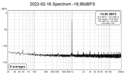
Specifically, relative to the impedance measurement, the noise level of the system assumes considerable importance, intended as the sum of the entire DAC + Analog Amplifier and Buffer + ADC chain.
Noise negatively affects the measurement of very low impedance values, vice versa the balance between your ADC channels together with the input impedance value of the input buffer alters the measurement of very high impedance values. (it is not known that the noise is only at high frequencies, there is also the noise at low frequencies below 100Hz typically introduced by power supply problems)
Precisely for this reason the latest version of REW has introduced a new calibration procedure that minimizes the defects of sound cards, the fact remains that the more performing the sound card, the better the final result. I collaborated with John by carrying out a series of measurements in order to validate the current calibration procedure.
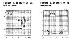
For the other measures, frequency response, RTA, distortion measures it is very important the linearity of the sound card the number of conversion bits the sampling frequency and also the distortion level. In short, it seems completely obvious to me that the performance of a measuring instrument is dependent on the quality of the individual modules that compose it. On one thing I can agree with you, specifically the impedance measurement, the distortion levels are not that relevant to the accuracy of the measurement.
Then everyone is free to think what they want, the world is beautiful because it is varied !!!
")
Greetings
Antonio