Impedance Calibration Test Jig - Release 5.20 Beta 38

tekuhn

Registered
Thread Starter
Joined
Jun 24, 2018
Posts
3
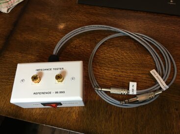
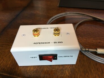
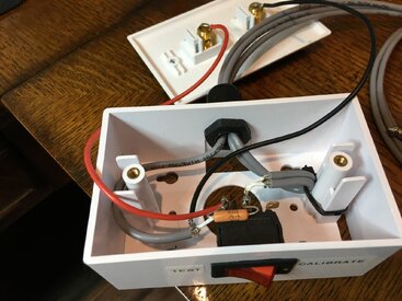
I apparently was looking at older documentation that gave the diagram for the test jig for using the sound card inputs and output to build an apparatus for testing driver impedance. I built one using a .1% 100Ω resistor. I also installed a switch to short across the resistor because it said that the calibration process required the load to be disconnected and the resistor to be shorted and the RSense value to be changed to 0Ω. I am looking at the docs for the newest beta version and there is no mention of shorting the resistor for the calibration process. Is that right - no need to short any more - just leave the RSense value to the actual measured value of the resistor and remove the driver load? Fantastic program, BTW. I'm really learning a lot and having a blast. I apologize if this has been answered elsewhere - I did attempt to look first..

Tom
 

Attachments

  • IMG_5098.JPG
    IMG_5098.JPG
    287.1 KB · Views: 96
  • IMG_5099.JPG
    IMG_5099.JPG
    209.7 KB · Views: 102
  • IMG_5097.JPG
    IMG_5097.JPG
    226.2 KB · Views: 100
I got the impedance test box going and it calibrated and works perfectly. Thank you for the help!

TF1225 Phase.jpg D220Ti Phase.jpg
 
[QUOTE = "tekuhn, message: 48191, membre: 13069"]
Je vous remercie. Je peux réaffecter l'interrupteur pour court-circuiteur les bornes de charge pour l'étalonnage des fils.
[/CITATION]

67/5000

Bravo pour ta petite boite, elle devrait servir d'exemple à l'aide de REW

Vous pouvez me donner un petit schéma de votre nouvelle connexion
 
No need for a switch with the latest version as the Rsense resistor is not shorted for calibration any more.
The two requirements are the precise value of the resistor and it must be a non-inductive one.
 
Last edited:
Back
Top