how to understand impulse ?

luigi191

New Member
Thread Starter
Joined
May 9, 2018
Messages
14
More  
Preamp, Processor or Receiver
NANO DIGI
Main Amp
DIY
Front Speakers
DIY SCANSPEAK
hi guy
could you help a poor french guy ? and sorry for my language !

i would like to adjust a new diy loudspeaker (2 way whith SCANSPEAK drivers) using REW and USB UMIK-1
my first measure is for time alignment betweeen drivers (acoustic timing reference on Right High , measure for Right High and Right Low/Mid )
but i have a problem with tweeter : setting start freq at 1000 and end freq at 20000 , results are incoherent (sometimes 0.27ms and fisrt negative peak sometimes 0.31 ms and second peak ) Randomly for 10 measure !!

1525860366-52.png

1525860326-51.png


So i'm unable to know the good value for delay and if the phase is inverted or not !

On the over side, if i put start freq at 2000 all results are uniform for 10 measure : delay 0.31ms and positive peak


i hope someone will understand me :praying:
 

John Mulcahy

REW Author
Joined
Apr 3, 2017
Messages
7,315
Looks like you have REW configured to put t=0 at the peak of the impulse. That might end up at the negative going or positive going peak depending on sweep settings. In any case, it isn't any good for time alignment, you will need to give REW a timing reference so that you can compare timing between measurements. You can select acoustic timing reference at the top of the Measure dialog, and use another speaker on the other channel to act as the reference. Make sure you don't change the distance between the reference speaker, your test speaker and the mic between your measurements.
 

luigi191

New Member
Thread Starter
Joined
May 9, 2018
Messages
14
More  
Preamp, Processor or Receiver
NANO DIGI
Main Amp
DIY
Front Speakers
DIY SCANSPEAK
Looks like you have REW configured to put t=0 at the peak of the impulse. That might end up at the negative going or positive going peak depending on sweep settings. In any case, it isn't any good for time alignment, you will need to give REW a timing reference so that you can compare timing between measurements. You can select acoustic timing reference at the top of the Measure dialog, and use another speaker on the other channel to act as the reference. Make sure you don't change the distance between the reference speaker, your test speaker and the mic between your measurements.
Thank you
If i choose acoustic référence in analysis préférences, t=0 at IR peak is always on
The distance don't change between speaker and mic
Why when measure the référence : delay is not zero ?
Now i try to change lenght at 128 or 256 or 1m and all results are different !
 

jtalden

Senior Member
Joined
May 22, 2017
Messages
888
Location
Arizona, USA
More  
Preamp, Processor or Receiver
Marantz AV7705 Pre/Pro
Main Amp
VTV 6 chnl NC252MP P-amp x 2
Additional Amp
Behringer DCX2496 x 2
Universal / Blu-ray / CD Player
OPPO BDP-103 Universal Player
Front Speakers
DIY SEAS H1456/H1212 Spkr x 5
Subwoofers
DIY JBL 2235H 15" SW x 2
Video Display Device
JVC DLA-X790R
Screen
Da-Lite Da-Snap 39105V - 92"
luigi191,
If you will post an mdat with the needed measurements. I can analyze the data and provide you with the best delay value to use.

let me know if you would like me to do that. If so, I will provide instructions for the required setup for the REW measurements.
 

luigi191

New Member
Thread Starter
Joined
May 9, 2018
Messages
14
More  
Preamp, Processor or Receiver
NANO DIGI
Main Amp
DIY
Front Speakers
DIY SCANSPEAK
luigi191,
If you will post an mdat with the needed measurements. I can analyze the data and provide you with the best delay value to use.

let me know if you would like me to do that. If so, I will provide instructions for the required setup for the REW measurements.
hooo yes great !!
tell me what you need
 

jtalden

Senior Member
Joined
May 22, 2017
Messages
888
Location
Arizona, USA
More  
Preamp, Processor or Receiver
Marantz AV7705 Pre/Pro
Main Amp
VTV 6 chnl NC252MP P-amp x 2
Additional Amp
Behringer DCX2496 x 2
Universal / Blu-ray / CD Player
OPPO BDP-103 Universal Player
Front Speakers
DIY SEAS H1456/H1212 Spkr x 5
Subwoofers
DIY JBL 2235H 15" SW x 2
Video Display Device
JVC DLA-X790R
Screen
Da-Lite Da-Snap 39105V - 92"
Measurements needed to determine MW x TW driver delay

Setup

  • Select one of the 2 speakers for these measurements - right or left.
  • Place the mic at 0.5-1.0 m in front of the speaker baffle.
  • Adjust the mic height so that it is approximately on the intended listening axis. [The line of sight from the intended listening position to the mid point between the 2 drivers.]
  • Confirm the XO filters are activated.
  • If old EQ filters are active that is okay, but EQ filters within the XO range are best disabled for this process.
  • Activate REW 'Acoustic Timing' for these measurements, if you know how to do this properly using the other speaker as the reference. [If you are not familiar with the proper setup and use of this REW acoustic timing feature you can skip this step]
  • All 3 measurements must be full range (50-20k Hz will work well)
  • 75-85 dB SPL for this testing is a reasonable level to set for the 2 drivers prior to the measurements.

Measure
  1. TW
  2. MW
  3. TW+MW [both drivers together]
Post the mdat containing these 3 measurements here.

Questions?
 

luigi191

New Member
Thread Starter
Joined
May 9, 2018
Messages
14
More  
Preamp, Processor or Receiver
NANO DIGI
Main Amp
DIY
Front Speakers
DIY SCANSPEAK
Measurements needed to determine MW x TW driver delay

Setup

  • Select one of the 2 speakers for these measurements - right or left.
  • Place the mic at 0.5-1.0 m in front of the speaker baffle.
  • Adjust the mic height so that it is approximately on the intended listening axis. [The line of sight from the intended listening position to the mid point between the 2 drivers.]
  • Confirm the XO filters are activated.
  • If old EQ filters are active that is okay, but EQ filters within the XO range are best disabled for this process.
  • Activate REW 'Acoustic Timing' for these measurements, if you know how to do this properly using the other speaker as the reference. [If you are not familiar with the proper setup and use of this REW acoustic timing feature you can skip this step]
  • All 3 measurements must be full range (50-20k Hz will work well)
  • 75-85 dB SPL for this testing is a reasonable level to set for the 2 drivers prior to the measurements.

Measure
  1. TW
  2. MW
  3. TW+MW [both drivers together]
Post the mdat containing these 3 measurements here.

Questions?
Ok 2 questions
I don't know what xo filter is
Is Full range not dangerous for tweeter ?
(No filter in speaker)
 

jtalden

Senior Member
Joined
May 22, 2017
Messages
888
Location
Arizona, USA
More  
Preamp, Processor or Receiver
Marantz AV7705 Pre/Pro
Main Amp
VTV 6 chnl NC252MP P-amp x 2
Additional Amp
Behringer DCX2496 x 2
Universal / Blu-ray / CD Player
OPPO BDP-103 Universal Player
Front Speakers
DIY SEAS H1456/H1212 Spkr x 5
Subwoofers
DIY JBL 2235H 15" SW x 2
Video Display Device
JVC DLA-X790R
Screen
Da-Lite Da-Snap 39105V - 92"
'XO' is shorthand for 'Crossover'. There are 2 active filters in the XO; a low pass filter and a high pass filter. Your 'system' includes a nano digi box which I assume is already setup to provide your chosen crossover function. With the XO active it protects the TW from the low frequencies just as it does in normal operation. There is thus no possibility of damage.

Setting a delay is irrelevant until the XO filters are selected and active as that decision impact the needed delay setting.
 

luigi191

New Member
Thread Starter
Joined
May 9, 2018
Messages
14
More  
Preamp, Processor or Receiver
NANO DIGI
Main Amp
DIY
Front Speakers
DIY SCANSPEAK
'XO' is shorthand for 'Crossover'. There are 2 active filters in the XO; a low pass filter and a high pass filter. Your 'system' includes a nano digi box which I assume is already setup to provide your chosen crossover function. With the XO active it protects the TW from the low frequencies just as it does in normal operation. There is thus no possibility of damage.

Setting a delay is irrelevant until the XO filters are selected and active as that decision impact the needed delay setting.
Yes ok !
I have active filter LR 24db/o low pass and high pass
I will do that tomorrow because children at home yet !
Thanks a lot
 

luigi191

New Member
Thread Starter
Joined
May 9, 2018
Messages
14
More  
Preamp, Processor or Receiver
NANO DIGI
Main Amp
DIY
Front Speakers
DIY SCANSPEAK
Measurements needed to determine MW x TW driver delay

Setup

  • Select one of the 2 speakers for these measurements - right or left.
  • Place the mic at 0.5-1.0 m in front of the speaker baffle.
  • Adjust the mic height so that it is approximately on the intended listening axis. [The line of sight from the intended listening position to the mid point between the 2 drivers.]
  • Confirm the XO filters are activated.
  • If old EQ filters are active that is okay, but EQ filters within the XO range are best disabled for this process.
  • Activate REW 'Acoustic Timing' for these measurements, if you know how to do this properly using the other speaker as the reference. [If you are not familiar with the proper setup and use of this REW acoustic timing feature you can skip this step]
  • All 3 measurements must be full range (50-20k Hz will work well)
  • 75-85 dB SPL for this testing is a reasonable level to set for the 2 drivers prior to the measurements.

Measure
  1. TW
  2. MW
  3. TW+MW [both drivers together]
Post the mdat containing these 3 measurements here.

Questions?


Hi
I did it , here is the mdat


  • Mic = OK
  • Confirm the XO filters are activated.= OK LR24 freq. 1800 Hz
  • no EQ
  • Acoustic Timing' for these measurements, TW is the reference.
  • All 3 measurements must be full range (50-20k Hz will work well) = OK
 

Attachments

  • pld1.mdat
    8.6 MB · Views: 28

AudiocRaver

Senior Reviewer
Staff member
Joined
Nov 21, 2016
Messages
974
Location
North Carolina, USA
More  
Preamp, Processor or Receiver
Onkyo TX-SR705 Receiver
Main Amp
Crown XLS 1502 DriveCore-2 (x2 as monoblock)
Additional Amp
Behringer A500 Reference Power Amplifier
Front Speakers
MartinLogan Electromotion ESL Electrostatic (x2)
Center Channel Speaker
Phantom Center
Surround Speakers
NSM Audio Model 5 2-Way (x2)
Subwoofers
JBL ES150P Powered Subwoofer (x2)
luigi191, you are in good hands.

Thanks, John.
 

jtalden

Senior Member
Joined
May 22, 2017
Messages
888
Location
Arizona, USA
More  
Preamp, Processor or Receiver
Marantz AV7705 Pre/Pro
Main Amp
VTV 6 chnl NC252MP P-amp x 2
Additional Amp
Behringer DCX2496 x 2
Universal / Blu-ray / CD Player
OPPO BDP-103 Universal Player
Front Speakers
DIY SEAS H1456/H1212 Spkr x 5
Subwoofers
DIY JBL 2235H 15" SW x 2
Video Display Device
JVC DLA-X790R
Screen
Da-Lite Da-Snap 39105V - 92"
luigi191,
This analysis will take 2 steps to deal with.

Step 1:
An initial check was done to confirm that acoustic timing worked properly for the 3 measurements. It initially appeared it did as the impulses were shifted from 0 ms by a typical amount expected. To confirm, A + B Arithmetic in REW was used to create 'TW+MW math'. We expect the SPL of 'TW+MW' (trace3) to exactly equal 'TW+MW Math' (trace 4) shown in the chart below. We can see that the SPL traces do not overlay and thus there was some problem with the acoustic timing. Possibly; "Wait for timing reference" was not active in REW, or possibly the mic was moved slightly between the 3 measurements. There are several possibilities. You may want to look into this if you plan on using this feature again.

SPL Error.jpg


Rather than sorting through the possibilities of the measurement error in the acoustic timing and running the testing again, we can determine the actual timing relationship between the TW and MW by analysis and manually shift the position of the MW impulse in REW accordingly.
That is possible as there is only one TW to MW timing that will result in a perfect SPL overlay.
That way we can still use this data to determine the delay needed. After some effort it was determined that a relative timing shift of 0.024ms was needed to achieve the actual current timing. Below, the SPL of 'TW+MW' (trace3) exactly equals the 'TW+MW Corrected' (trace 6) using this timing adjustment.

SPL Adjusted.jpg


I will use this corrected TW to MW timing in Step 2 to determine the additional delay needed to achieve the ideal timing relationship between the 2 drivers. I will try to get back to this effort later today.
 

luigi191

New Member
Thread Starter
Joined
May 9, 2018
Messages
14
More  
Preamp, Processor or Receiver
NANO DIGI
Main Amp
DIY
Front Speakers
DIY SCANSPEAK
luigi191,
This analysis will take 2 steps to deal with.

Step 1:
An initial check was done to confirm that acoustic timing worked properly for the 3 measurements. It initially appeared it did as the impulses were shifted from 0 ms by a typical amount expected. To confirm, A + B Arithmetic in REW was used to create 'TW+MW math'. We expect the SPL of 'TW+MW' (trace3) to exactly equal 'TW+MW Math' (trace 4) shown in the chart below. We can see that the SPL traces do not overlay and thus there was some problem with the acoustic timing. Possibly; "Wait for timing reference" was not active in REW, or possibly the mic was moved slightly between the 3 measurements. There are several possibilities. You may want to look into this if you plan on using this feature again.

View attachment 7996

Rather than sorting through the possibilities of the measurement error in the acoustic timing and running the testing again, we can determine the actual timing relationship between the TW and MW by analysis and manually shift the position of the MW impulse in REW accordingly.
That is possible as there is only one TW to MW timing that will result in a perfect SPL overlay.
That way we can still use this data to determine the delay needed. After some effort it was determined that a relative timing shift of 0.024ms was needed to achieve the actual current timing. Below, the SPL of 'TW+MW' (trace3) exactly equals the 'TW+MW Corrected' (trace 6) using this timing adjustment.

View attachment 7997

I will use this corrected TW to MW timing in Step 2 to determine the additional delay needed to achieve the ideal timing relationship between the 2 drivers. I will try to get back to this effort later today.

Good job Jtalden :T
"wait for timing reference" was active
mic was not moved , sure 100%
i will try tomorow a new A+B to compare

Please tell me how to find the 0.024ms :help:
Do you want me to make measurements by seting 0.024 delay in DSP ?

ps: how to create trace 6 (shifted) ?


:T
 
Last edited:

jtalden

Senior Member
Joined
May 22, 2017
Messages
888
Location
Arizona, USA
More  
Preamp, Processor or Receiver
Marantz AV7705 Pre/Pro
Main Amp
VTV 6 chnl NC252MP P-amp x 2
Additional Amp
Behringer DCX2496 x 2
Universal / Blu-ray / CD Player
OPPO BDP-103 Universal Player
Front Speakers
DIY SEAS H1456/H1212 Spkr x 5
Subwoofers
DIY JBL 2235H 15" SW x 2
Video Display Device
JVC DLA-X790R
Screen
Da-Lite Da-Snap 39105V - 92"
Please tell me how to find the 0.024ms

I don't have time to explain the rather detailed process. There is no longer any need for this time consuming process. Acoustic timing works perfectly well when the process is setup correctly and the accuracy is has been confirmed.

To confirm acoustic timing is working properly;
Either:
  • Use your current setup and take a series of TW measurements. Normal operation is indicated by the impulse overlay chart showing all the impulses falling directly on top of each other. It should look like one trace. Zoom in all the way on the time axis to readily show up any time shift in the series. You can repeat this using the MW and well, but it is a little harder to see a shift as the impulse peak is not as sharp.
Or:
  • Repeat the series you just ran and use REW A + B Arithmetic on the TW and MW as I did. The overlay of the SPL of the measured vs the math traces should be identical.
Do you want me to make measurements by seting 0.024 delay in DSP ?

There is no need for my analysis. The correct timing has now been set in the current data and will serve well for the analysis. After the recommended final delay is determined that should be applied and the measurements then repeated. That will confirm that the delay is both calculated and set correctly.

how to create trace 6 (shifted) ?

Trace 6 is Trace 1 plus Trace 5 (A + B arithmetic). It is; 'TW' + 'MW-copy +.024ms'.
 

jtalden

Senior Member
Joined
May 22, 2017
Messages
888
Location
Arizona, USA
More  
Preamp, Processor or Receiver
Marantz AV7705 Pre/Pro
Main Amp
VTV 6 chnl NC252MP P-amp x 2
Additional Amp
Behringer DCX2496 x 2
Universal / Blu-ray / CD Player
OPPO BDP-103 Universal Player
Front Speakers
DIY SEAS H1456/H1212 Spkr x 5
Subwoofers
DIY JBL 2235H 15" SW x 2
Video Display Device
JVC DLA-X790R
Screen
Da-Lite Da-Snap 39105V - 92"
Step 2 is completed.
  • A TW delay increase of 0.16ms is needed to properly time the XO handoff.
  • The relative polarity of the 2 drivers is already favorable. The TW is now negative and MW is positive. They can be left as they are, but it is more conventional to apply positive polarity to the TW and adjust the other drivers as needed. If you want to make that change then just change the polarity of both drivers.

Below are some charts to illustrate the impact of the change:
SPL Comparison.jpg


Current Phase Tracking:
Phase Initial.jpg


Corrected Phase Tracking (with TW +0.16 ms delay):
Phase Tracking.jpg

SPL XO Range Support.jpg


Notes:
  • The charts reflect the current polarities of the drivers. If they are both reversed the charts would be the same except the phase would be shifted 180° from the values shown here. Phase tracking would not be impacted. It is unlikely to impact the sound quality.
  • With the new timing the direct sound from both drivers will arrive at the LP at the same time for all frequencies in the XO range. This will create a stable frontal lobe and maximize the chance of a stable stage image. There will be minimal impact to changes in vertical listening position. The SPL consistency in the horizontal direction is also maximized.
  • The next step is to repeat the 3 measurements using the same setup, but with the +0.16ms TW delay setting so we can then confirm these calculated results.
 

luigi191

New Member
Thread Starter
Joined
May 9, 2018
Messages
14
More  
Preamp, Processor or Receiver
NANO DIGI
Main Amp
DIY
Front Speakers
DIY SCANSPEAK
hi
there is the 3 measurements using TW +0.16ms delay
It's perfect !!
waiting for your analysis

I'm so sorry to bother you, can you explain to me how to calculate the +0.16ms ? in case of another speaker ,i d'ont want to ask you every time
 

Attachments

  • pld2.mdat
    8.5 MB · Views: 13

John Mulcahy

REW Author
Joined
Apr 3, 2017
Messages
7,315
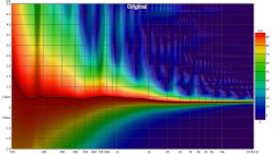
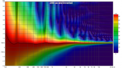
Looking at the wavelet spectrogram plots I wonder if a better overall result might be obtained by shifting the tweeter IR by -250 us (approx) and inverting it (based on that latest measurement). Seems to have a flatter peak energy trace.

spec1.png spec2.png
 

jtalden

Senior Member
Joined
May 22, 2017
Messages
888
Location
Arizona, USA
More  
Preamp, Processor or Receiver
Marantz AV7705 Pre/Pro
Main Amp
VTV 6 chnl NC252MP P-amp x 2
Additional Amp
Behringer DCX2496 x 2
Universal / Blu-ray / CD Player
OPPO BDP-103 Universal Player
Front Speakers
DIY SEAS H1456/H1212 Spkr x 5
Subwoofers
DIY JBL 2235H 15" SW x 2
Video Display Device
JVC DLA-X790R
Screen
Da-Lite Da-Snap 39105V - 92"
waiting for your analysis

The delay setting looks good.
Be advised though, Your acoustic timing is still not repeatable. This needs to be corrected before using the process below.

...can you explain to me how to calculate the +0.16ms ?

Given this particular situation/setup the basic steps are:
  • Measure TW and MW with acoustic timing properly applied.
  • Offset the impulse of both measurements by the same amount such that the initial peak of the TW impulse is located near 0 ms.
  • Use REW 'All SPL' control panel to duplicate the MW measurement. This 'MW-Copy' is the measurement impulse we adjust to find the best phase tracking. The original TW and the MW impulses will not be moved again.
  • Set the smoothing to 1/48 octave for all 3 measurements.
  • Open the REW phase overlay chart and uncheck the MW measurement and thus view the phase tracking of the TW and the MW-Copy in the XO frequency range of interest.
  • Now using trial and error, move the MW-Copy impulse location manually until the closest phase tracking is found. It may happen that the best tracking is found with the MW-Copy impulse inverted, so it is best to try both ways.
  • When the closest phase tracking is found, the change in delay timing that is needed can be measured on the impulse overlay chart. Use 'Ctrl-right button drag' to measure the time shift from the original MW measurement impulse to the new location of the MW-Copy impulse.
Note:
This process often needs to be adjusted for different setup situations.
 

jtalden

Senior Member
Joined
May 22, 2017
Messages
888
Location
Arizona, USA
More  
Preamp, Processor or Receiver
Marantz AV7705 Pre/Pro
Main Amp
VTV 6 chnl NC252MP P-amp x 2
Additional Amp
Behringer DCX2496 x 2
Universal / Blu-ray / CD Player
OPPO BDP-103 Universal Player
Front Speakers
DIY SEAS H1456/H1212 Spkr x 5
Subwoofers
DIY JBL 2235H 15" SW x 2
Video Display Device
JVC DLA-X790R
Screen
Da-Lite Da-Snap 39105V - 92"
Looking at the wavelet spectrogram plots I wonder if a better overall result might be obtained by shifting the tweeter IR by -250 us (approx) and inverting it (based on that latest measurement). Seems to have a flatter peak energy trace.

Hi John,
It's very possibly better. These 2 alignments sparked a very old question of mine that I have never really resolved. In any case both are very good options and provide excellent SPL fill/support in the XO range.
I don't know if there would be a significant difference to the sound at this 2 kHz XO range, but I have heard a noticeable difference between these two options in my SW/mains handoff so it is worth a listen to see if there is a preference.

Which one best maintains the same arrival time of the direct sound from the 2 drivers? I was wanting to use the one that provides the best XO range timing. The theory being that it best allows PEQ and followed by an FIR phase correction filter to best approach an ideal Impulse and step response.


luigi191

New Member
Thread Starter
Joined
May 9, 2018
Messages
14
More  
Preamp, Processor or Receiver
NANO DIGI
Main Amp
DIY
Front Speakers
DIY SCANSPEAK
Looking at the wavelet spectrogram plots I wonder if a better overall result might be obtained by shifting the tweeter IR by -250 us (approx) and inverting it (based on that latest measurement). Seems to have a flatter peak energy trace.

View attachment 8021 View attachment 8022
Thk John
i'll try the 2 alignments as soons as system is ok
it's possible i'll don't hear a difference ....i'm not a specialist
 

luigi191

New Member
Thread Starter
Joined
May 9, 2018
Messages
14
More  
Preamp, Processor or Receiver
NANO DIGI
Main Amp
DIY
Front Speakers
DIY SCANSPEAK
The delay setting looks good.
Be advised though, Your acoustic timing is still not repeatable. This needs to be corrected before using the process below.
why ? on the second measurments ; 'TW+MW Math' is exactly equal the 'TW+MW'
 

luigi191

New Member
Thread Starter
Joined
May 9, 2018
Messages
14
More  
Preamp, Processor or Receiver
NANO DIGI
Main Amp
DIY
Front Speakers
DIY SCANSPEAK
Thank you very much Jtladen for your process :T:T:T:T:T:T:T
 

jtalden

Senior Member
Joined
May 22, 2017
Messages
888
Location
Arizona, USA
More  
Preamp, Processor or Receiver
Marantz AV7705 Pre/Pro
Main Amp
VTV 6 chnl NC252MP P-amp x 2
Additional Amp
Behringer DCX2496 x 2
Universal / Blu-ray / CD Player
OPPO BDP-103 Universal Player
Front Speakers
DIY SEAS H1456/H1212 Spkr x 5
Subwoofers
DIY JBL 2235H 15" SW x 2
Video Display Device
JVC DLA-X790R
Screen
Da-Lite Da-Snap 39105V - 92"
why ? on the second measurments ; 'TW+MW Math' is exactly equal the 'TW+MW'

Yes that's right. The relative timing of TW vs MW were correct so the TW+MW Math matched the TW+MW Measurement for SPL. The problem was that the TW+MW measurement was shifted in time compared to the 2 driver measurements. Thus, the relative location of the TW+MW Math Vs TW+MW measurement impulse was shifted. I didn't consider that option when I suggested the 2nd way to confirm the acoustic timing accuracy using SPL. Had you used the data for delay timing per the procedure the delay found would have been correct as its based on the first 2 measurements. The time shift to the 3rd measurement does still indicate that your acoustic timing setup is not as reliable as it should be yet.

I used the 1st option; a series of TW measurements and a series of MW measurements. Each series should fall on top of themselves. The longer the series, the greater the confidence. Anything over 6 each with no significant shift is pretty safe. I occasionally get a very small shift (maybe 1 sample). That amount of shift is insignificant.

Very rarely I see a larger shift so, when I am being very careful in my analysis, I take 3-4 TW and MW measurements, review the impulse overly chart to choose which 2 to use, then I delete the others. [Trust, but verify.]
 
Top Bottom