Gedlee Abbey-old build new thread

Matthew J Poes

AV Addict
Thread Starter
Joined
Oct 18, 2017
Messages
1,903
0272CAA2-DE15-4E4A-9D34-0F964CDDF596.jpeg 26317E6D-8AB8-4D59-9187-E0928F3E02C2.jpeg 9328F35C-69E5-40BE-BA79-DA1E87F3F131.jpeg 2EB8D777-5F29-4F20-99C1-8E1509BA1A5A.jpeg C8F9A920-750C-48E7-AB60-21FE5A2E2A17.jpeg EC42C338-43C2-4868-8FA4-6C5BD253A3E1.jpeg 7CECCD8C-9FFB-46DF-879E-447A6AA57152.jpeg 27BEBEC4-2837-4FAC-8489-119B1574A973.jpeg 7C80A591-7A69-434B-AAE3-A6E880146840.jpeg

I built these in 2009 but recently rediscovered the pictures. I thought I would share. I keep telling myself I'm going to refurbish them with new paint, but can't be without them that long.

In their new home 2017
5ECA1D85-0FE2-4DC1-980C-2BDAAEB2E4F5.jpeg

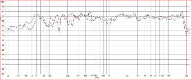
Some old measurements (ATB Precison Pro)
7C23E7B2-D5BF-4415-B4E3-D6709F656BAD.jpeg 223F6C79-8B27-4402-9AD1-F284EA20E7DD.jpeg 562C7A5C-3273-4B84-9DAF-8CDEEBBC5E8B.jpeg

The excessive smoothing is an artifact of the stitching process ATB uses. If you take two measurements that are each smoother and stitch them together you get smoothing to the next level. So two 1/6 smoothed files gives you a 1/3 smoothed final response. These are nearfiele measurements in a room. There is a lot of room garbage in the measurements still.
 

Attachments

  • BA77FA10-55DC-47A2-A600-80754BC1C5BB.jpeg
    BA77FA10-55DC-47A2-A600-80754BC1C5BB.jpeg
    78.3 KB · Views: 226

Jororaitchev

Member
Joined
May 17, 2017
Messages
86
Location
Sofia - Bulgaria
More  
Preamp, Processor or Receiver
Marantz 6009
Universal / Blu-ray / CD Player
OPPO105D
Front Speakers
DIY_ "J&N"
Center Channel Speaker
DIY_ "J&N"
Surround Back Speakers
DIY_ "J&N"
Very good job!

[/QUOTE]
I built these in 2009 but recently rediscovered the pictures. I thought I would share. I keep telling myself I'm going to refurbish them with new paint, but can't be without them that long.
[/QUOTE]
Very easy solution - new project.
PS
I have small remarks about the construction of the filter / the location of the elements in the crossover/.
 

tripplej

AV Addict
Joined
Jul 13, 2017
Messages
6,881
More  
Preamp, Processor or Receiver
NAD T-777
Universal / Blu-ray / CD Player
Oppo 103 Blu Ray Player
Front Speakers
7 Paradigm Reference series 8" in ceiling speakers
Subwoofers
2 Paradigm SE Subs
Other Speakers or Equipment
Nintendo Wii U Gaming Console
Video Display Device
Samsung UN75F8000 LED TV
Remote Control
Universal Remote MX-450
Streaming Subscriptions
Sony PS4 Gaming Console, Panamax MR-5100 Surge
Wow, very nice speakers.
 

Matthew J Poes

AV Addict
Thread Starter
Joined
Oct 18, 2017
Messages
1,903
Very good job!
I built these in 2009 but recently rediscovered the pictures. I thought I would share. I keep telling myself I'm going to refurbish them with new paint, but can't be without them that long.
[/QUOTE]
Very easy solution - new project.
PS
I have small remarks about the construction of the filter / the location of the elements in the crossover/.[/QUOTE]

What is your comment?

I layed them out precisely so that the inductors would not interact with each other and the resistors had room for cooling.
 

Jororaitchev

Member
Joined
May 17, 2017
Messages
86
Location
Sofia - Bulgaria
More  
Preamp, Processor or Receiver
Marantz 6009
Universal / Blu-ray / CD Player
OPPO105D
Front Speakers
DIY_ "J&N"
Center Channel Speaker
DIY_ "J&N"
Surround Back Speakers
DIY_ "J&N"
I will try to explain:
- Inductors are positioned in a slightly different way, if the one is horizontal, the other must be vertically positioned.
- all plastic connectors must be discarded/ they are only valid for the initial measurements of the filter/ and in their place made of tin-bonded.
 

Attachments

  • cross.pdf
    1.2 MB · Views: 80

Matthew J Poes

AV Addict
Thread Starter
Joined
Oct 18, 2017
Messages
1,903
I will try to explain:
- Inductors are positioned in a slightly different way, if the one is horizontal, the other must be vertically positioned.
- all plastic connectors must be discarded/ they are only valid for the initial measurements of the filter/ and in their place made of tin-bonded.
The inductors are positioned so as not to interact. If it doesn't appear that way it's an optical illusion. For scale please understand that is a 14"X30" panel.

The inductors closest together are at different angles and orientations (two are upright but at right angles, one is lying down. The distance is about 10-15cm from each other as well. Can you please explain how this is not right. How they should be moved?

http://www.troelsgravesen.dk/coils.htm

The euro strips are fine for final assbly and were the preferred assembly approach of Dr Earl Geddes, the designer. Euro strips are uses all the time in actual manufacture electronics so I see no issue. I've had these working fine since 2009 and the strips allow quick parts replacement if anything fails.
 
Last edited:

Jororaitchev

Member
Joined
May 17, 2017
Messages
86
Location
Sofia - Bulgaria
More  
Preamp, Processor or Receiver
Marantz 6009
Universal / Blu-ray / CD Player
OPPO105D
Front Speakers
DIY_ "J&N"
Center Channel Speaker
DIY_ "J&N"
Surround Back Speakers
DIY_ "J&N"
The inductors are positioned so as not to interact. If it doesn't appear that way it's an optical illusion. For scale please understand that is a 14"X30" panel.

Yes, a really huge volume of filter layout, usually, the size is much smaller.

The inductors closest together are at different angles and orientations (two are upright but at right angles, one is lying down. The distance is about 10-15cm from each other as well. Can you please explain how this is not right. How they should be moved?

I'm sorry, maybe you agree that the pictures are not the best, I'm just a side observer, I can not know the details!

http://www.troelsgravesen.dk/coils.htm

The euro strips are fine for final assbly and were the preferred assembly approach of Dr Earl Geddes, the designer. Euro strips are uses all the time in actual manufacture electronics so I see no issue. I've had these working fine since 2009 and the strips allow quick parts replacement if anything fails.

Then, as the concept is clarified, they are not needed / how many times since 2009 you have changed elements /?
All the best,
Joro
 

Matthew J Poes

AV Addict
Thread Starter
Joined
Oct 18, 2017
Messages
1,903
Then, as the concept is clarified, they are not needed / how many times since 2009 you have changed elements /?
All the best,
Joro

I'm not sure what you are saying? Are you suggesting that once a crossover is finalized the plastic eurostrips aren't needed? If so I think you will have to accept that we disagree on this point. They make a solid mechanical connection that still allows repairs as needed. Even if parts were never changed it doesn't change the fact that they do no harm. This approach came from Earl Geddes who has used it for more than 30 years at this point and stuck with it. I find this a really minor issue to harp on.

When the speaker was finished the transfer function of the crossover was measured and assessed. In fact variations in the transfer function were discovered as a result of part tolerance issues and I later went back and hand matched the inductors and resistors to get back to the right transfer function. This was done in communication with Earl Geddes to confirm results.

As for changing parts, I have done so a few times. The crossover uses a parallel capacitor of small value on the series resistor of the L-Pad to change the high frequency slope. Changing this value is helpful depending on if the speaker is used behind a screen or not. I've gone back and forth and typically change the value of this capacitor.

Additionally the speaker can handle quite a bit of power. The midbass can handle more than 1000 watts RMS and quite a bit more with "music" power. There are a few parts that could take a bit of current during loud passages such as the series resistor on the tweeter and the parallel resistor on the leg of the capacitor in the woofer lowpass. One of these failed on me and so I replaced it with a higher wattage part. Having the ability to unscrew and replace has been very helpful.

Again though I see this as all pretty minor stuff that has zero impact on sound quality.
 

Jororaitchev

Member
Joined
May 17, 2017
Messages
86
Location
Sofia - Bulgaria
More  
Preamp, Processor or Receiver
Marantz 6009
Universal / Blu-ray / CD Player
OPPO105D
Front Speakers
DIY_ "J&N"
Center Channel Speaker
DIY_ "J&N"
Surround Back Speakers
DIY_ "J&N"
This is just one of my opinions. It does not matter what I think, it is important that your own speakers give you pleasure.
Тhis is statement of a person claiming experience in building construction in the DIY audio speakers projects I'm sorry if I was offended you with something!
I have never claimed that i can to speak and write English / I speak 4 another languages /, There is always a language barrier (especially for me), I was trying to tell you that in my projects I will never use such terminals.
 

Matthew J Poes

AV Addict
Thread Starter
Joined
Oct 18, 2017
Messages
1,903
This is just one of my opinions. It does not matter what I think, it is important that your own speakers give you pleasure.
Тhis is statement of a person claiming experience in building construction in the DIY audio speakers projects I'm sorry if I was offended you with something!
I have never claimed that i can to speak and write English / I speak 4 another languages /, There is always a language barrier (especially for me), I was trying to tell you that in my projects I will never use such terminals.

I appoligize Joro. I know you are trying to give advice and English isnt your first language.

Your Speakers look beautiful and your attention to detail is outstanding. I certainly would not mean to imply otherwise.

The statements I made were over confusion of the problem. The inductors were intentionally placed to avoid interaction of the inductors. If you believe i did that wrong I'm happy to have you show me where and how you would have done it differently. Remember that that there are three inductors on the high pass section and so I am limited to the arrangements. I thought that I had chosen the correct arrangements. At the time of construction I had Dr Geddes, PhD acoustical physicist with 30+ years experience designing and building speakers oversee my construction, including the layout of the inductors. Not only did he show me how to arrange the inductors and sign off on the final product, but he reviewes my transfer function measurements and indicated they were correct. This is why I think it's right. If you have experience to suggest it's not I'm open to learning what could be wrong and investigating if something is wrong.

Same with the Euro barrier strips. I had never used those for crossover work. I always soldered. When Dr Geddes sent me the kit for his speaker the instructions said to use these barrier strips. I expressed concern to him about reliability and sound quality. He replied (more than once) that this is a more reliable connection for high voltage and high current apications, was used inside pro speakers before PCB came about (which he says was a switch for automation and not reliability). He also sent me a paper comparing connection resistance of crimped, screw clamped, and soldered. Solder had the highest connection resistance. It was his assurances that led me to use and keep the barrier strips. If you have good reason to doubt his claims, such as your own tests, I'm open to hearing it. Otherwise I see no reason to change it to solder connections (and there are solder connections in some places where that made more sense).

While I have designed and built speakers from end to end, this speaker is not my design.
 

Jororaitchev

Member
Joined
May 17, 2017
Messages
86
Location
Sofia - Bulgaria
More  
Preamp, Processor or Receiver
Marantz 6009
Universal / Blu-ray / CD Player
OPPO105D
Front Speakers
DIY_ "J&N"
Center Channel Speaker
DIY_ "J&N"
Surround Back Speakers
DIY_ "J&N"
When we talk about types of electrical connections we always respect the law of Om.
Om's law is at the heart of electrical engineeringand who is trying to challenge it obviously doesn't have to be on the planet "Earth".
If you have a An electrical point connected in a different way and realized with different material, the losses are different .This is a "Base of Electrical Engineering" and the results are proved in laboratory research.
A 24-carat gold-plated universal bracelet and connection with a silvers solder, can not be compared to the loss electrical mechanical connections.There are specific requirements.If long connections between elements are acceptable when constructing filters for audio speakers , this is not allowed when building a TV amplifier,because the wavelength is different.
In yours case, the filter elements are located in "Huge" space and they can not interact, the weak link is the large number of terminals, i can repeat this so many times, if you want, we can make a debate on the topic with Dr Geddes , can be interesting for the audience.

P.S.
By education I am an electric engineer with specialty "Electric Power Plants, Networks and Systems", I graduated in 1982.
For this not a small amount of time,I have worked with the following technical parameters:
voltages from 0.5V to 110000 V;
currents from 0, 01A to 1000 kA.
transformers - from 0,05-1000 kVA.
I'm not an audio engineer, but I understand from electrical losses .
 
Top Bottom