Circuit Transfer Function Measurement with REW

Rob Campbell

Registered
Thread Starter
Joined
Jan 3, 2018
Messages
3
Is it possible to measure the phase and amplitude response of a signal level circuit such as an active (op amp) filter using REW and a sound card like the Behringer UCA202?

Thanks, much!
 

John Mulcahy

REW Author
Joined
Apr 3, 2017
Messages
7,324
Yes, it will correct it to flat so you get the response of the device you are measuring and not the soundcard.
 

Milsdrewbulch

Registered
Joined
May 26, 2017
Messages
3
Location
Sydney
More  
Preamp, Processor or Receiver
diy
Main Amp
diy
I have tried this for several DIY LR4 active crossovers and am confused by the phase traces. If I measure a simple loop-back through the sound card I get a flat phase line. (Focusrite 2i2 with cal file loaded). If I sweep through the LR4 high pass section I get what I'd expect to see, but the phase response through the LP section has unexpected shape. The LR4 is working perfectly and the amplitude traces look great. I see this on all the active crossovers that I've built and they all work fine. Here is an example of a 530Hz crossover that displays an "odd" REW LP phase curve:

[trouble with OneDrive link]

Have I missed a setting?

Cheers,
Ian
 

Attachments

  • funnyphase.jpg
    funnyphase.jpg
    85.1 KB · Views: 37

John Mulcahy

REW Author
Joined
Apr 3, 2017
Messages
7,324
Probably missing a timing reference, so the t=0 point is being set as the peak of the response. There are a couple of things you can do:
- Use the Estimate IR Delay feature in the graph controls to have REW estimate a correct t=0 position
- Use a loopback connection on the other soundcard channel as a timing reference, telling REW that with the setting on the Measure dialog just below the SPL/Impedance buttons
 

Milsdrewbulch

Registered
Joined
May 26, 2017
Messages
3
Location
Sydney
More  
Preamp, Processor or Receiver
diy
Main Amp
diy
Thank you so much Mr Mulcahy for this answer and in general for your most brilliant software. I did what you said and now see a proper-looking LP phase trace per attachment. Probably telling me that I could have matched the capacitors a bit better. :)
 

Attachments

  • shiftedIRoverlay.jpg
    shiftedIRoverlay.jpg
    89.1 KB · Views: 25

John Mulcahy

REW Author
Joined
Apr 3, 2017
Messages
7,324
Best check the HP as well, or measure both with a loopback connection in place to ensure they have a common reference.
 

Milsdrewbulch

Registered
Joined
May 26, 2017
Messages
3
Location
Sydney
More  
Preamp, Processor or Receiver
diy
Main Amp
diy
That was HP and LP overlaid. Not with loopback but with "Estimate IR Delay" and shift. Looks good enough. Thanks.
 

mboxler

Registered
Joined
Dec 4, 2021
Messages
5
I purchased a UCA202 before reading about the issues with it. I've been using my PC's line in/line out and thought I'd give it a try.

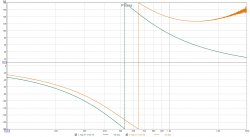
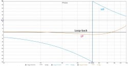
I'm using it to test my crossover build, and get a puzzling result. I created a calibration file, and the orange plot is the voltage across the amplifier output. The blue plot is the high pass voltage across the driver. As you can see, the voltage from 20 hz to 160 hz measures "backwards". It's as if the UCA202 has trouble measuring low voltages at low frequencies. Is this a normal issue with the UCA202, or is there a setting on it's line in that I can't seem to find?

If this is normal with the UCA202 I'll go back to the line in on my PC.

UCA202.jpg
 

John Mulcahy

REW Author
Joined
Apr 3, 2017
Messages
7,324
The UCA202 has issues with low frequency crosstalk that give poor impedance results at low frequencies.
 
Top Bottom