TIPS for Selecting Targets and Crossover Points...

Joe Fan

New Member
Thread Starter
Joined
Jan 13, 2021
Messages
7
Hi Guys
Could you please share your steps on how you go about designing your Audiolense targets and crossover points?
I'm designing it based on measured frequency response from the listening seat?
Should I measure 1 meter from the speakers?
Is there anything else that should be a factor besides measured frequency response?
Just trying to get a flat frequency response without more than 10 dB loss.

Thanks
 

Omid

Member
Joined
May 28, 2017
Messages
131
If you haven't already read it, I 'd highly recommend reading Mitch Barnett's article (and after that his book).
 

juicehifi

Audiolense
Staff member
Joined
Feb 5, 2018
Messages
701
I recommend that you read the tutorial in the help file.

There are three principally profiles in the Audiolense help file. One is straight line through the pass band, the other is close to the the Bruel & Kiaer curve, which is somewhat convex, the third has a lift in the bass which also gives it a somewhat concave shape. All the three shapes have a downtilt towards the high frequencies.

There are seasoned listeners in all three camps. If you haven't decided what you like, you should experiment with all three of them. The curvature has a profound impact on the timbre of various instruments and voices ( the three shapes).

How much you tilt the target has less impact on the timbre, but an impact on how warm or airy it sounds.

How you round off the target response in the bass sometimes has an impact on the sensation of speed and slam, so you should experiment with that too.

To my ears, the same targets tend to travel pretty well across rooms and systems, but people have different preferences. You need to find yours.
 

Joe Fan

New Member
Thread Starter
Joined
Jan 13, 2021
Messages
7
Thanks for all the help
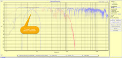
If you were me where would you crossover with this measurement?
I thought I'd put it where the dip is, not sure if that's the best place.
Could I improve the target so I don't get 10-17 db loss?
I was thinking of maxing out the sensitivity and using a low power tube amp.
 

Attachments

  • Audiolense.jpg
    Audiolense.jpg
    281.3 KB · Views: 200

jjazdk

Member
Joined
Aug 17, 2018
Messages
95
Without knowing anything about your speakers, amplifiers or loudness needs, it is impossible to make a recommendation.
 

Omid

Member
Joined
May 28, 2017
Messages
131
You have a very wide overlap between the two drives. I can see the dilemma. You could pick up a large variety of points for the crossover. What I would suggest doing is running a sweep in REW to measure the distortion level of each drive (average 8 sweeps 4M long each to lower the noise floor). You may find one drive ‘s distortion goes way up as it starts playing outside of its range of comfort. That might give you an indication of where to crossover to minimize distortion.
 

juicehifi

Audiolense
Staff member
Joined
Feb 5, 2018
Messages
701
There are a couple of things to consider here. One is how high the sub plays well, and how low the speaker plays well. The other, which touches more base with your question is, to pick a point where the two drivers integrate as well as possible. Here the sub has a dip while the main speaker has a sort of peak. So they could be out of phase there and in phase in the rest of the crossover region. They are however unlikely to be completely out of phase with each other, so it may work out fine. In general it is best to cross over in a region where the two driver have a similar phase behavior. Either a quiet region or a region where they share the same dips (although there are exceptions with the dips, because sometimes one can be 180* reversed to the other.

What I would do was to simply generate a filter where you are now and examine the simulated response as well as the correction filters. If the drivers are working against each other you will see some peaks in the correction filters, and perhaps get a dip in the simulation as well.

If I had one shot on picking the best crossover point - without knowing anything about your speakers - I would have tried 120 Hz. It looks like a quiet region for both. But this is an area where it is worthwhile to do some experimentation. And some times the crossover point can have a profound influence on the sound quality that doesn't show up in the charts at all.
 

2234rew

Member
Joined
Nov 24, 2020
Messages
271
What I would do was to simply generate a filter where you are now and examine the simulated response as well as the correction filters. If the drivers are working against each other you will see some peaks in the correction filters, and perhaps get a dip in the simulation as well.

Hi @juicehifi

(I love the ability to quote parts of a someone's post on this forum - couldn't do that on the Google forum)

Regarding the part I quoted here.

So if we don't have any peaks or dips around the XO point on BOTH correction filter and simulation, then can we be reasonably comfortable we've picked a good XO point objectively?
 

2234rew

Member
Joined
Nov 24, 2020
Messages
271
Thanks for all the help
If you were me where would you crossover with this measurement?
I thought I'd put it where the dip is, not sure if that's the best place.
Could I improve the target so I don't get 10-17 db loss?
I was thinking of maxing out the sensitivity and using a low power tube amp.

Can you share your correction filter and simulation graphs also?

Keeping your crossover point the same as you had in your image here.
 

juicehifi

Audiolense
Staff member
Joined
Feb 5, 2018
Messages
701
Hi @juicehifi

(I love the ability to quote parts of a someone's post on this forum - couldn't do that on the Google forum)

Regarding the part I quoted here.

So if we don't have any peaks or dips around the XO point on BOTH correction filter and simulation, then can we be reasonably comfortable we've picked a good XO point objectively?
Yes.
 

Joe Fan

New Member
Thread Starter
Joined
Jan 13, 2021
Messages
7
Thank you, I would not have thought of crossing on the quite regions,
I was thinking the opposite, maximize on the quite region and cross where it's messy lol
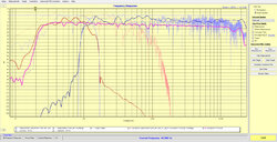
So I followed your advise and crossed at 120Hz and narrowed the width, see attached.
Does this look ok or could be improved on more?
Losing 10-17dB on the simulated result, is this typical?
 

Attachments

  • Audiolense2.jpg
    Audiolense2.jpg
    215.9 KB · Views: 132

2234rew

Member
Joined
Nov 24, 2020
Messages
271
Thank you, I would not have thought of crossing on the quite regions,
I was thinking the opposite, maximize on the quite region and cross where it's messy lol
So I followed your advise and crossed at 120Hz and narrowed the width, see attached.
Does this look ok or could be improved on more?
Losing 10-17dB on the simulated result, is this typical?

Did you have the correction response and simulated response, with your original 80Hz crossover?

It would be helpful to learn and see how that looked, to compare with your new crossover point.

Can you share that?
 

juicehifi

Audiolense
Staff member
Joined
Feb 5, 2018
Messages
701
^^Yes, looking all right.

you are losing approximately 7dB of gain here, which is moderate. I base that on the correction filters. The gain of the simulation is misleading as far as gain goes.
 

2234rew

Member
Joined
Nov 24, 2020
Messages
271
^^Yes, looking all right.

you are losing approximately 7dB of gain here, which is moderate. I base that on the correction filters. The gain of the simulation is misleading as far as gain goes.

Hi Bernt,

Just so I can get into your head (for calculations), when looking at correction curve only, how do you get losing 7dB of gain?

Can you markup his plot to show this 7dB loss? As a teaching exercise.
 

Joe Fan

New Member
Thread Starter
Joined
Jan 13, 2021
Messages
7
^^Yes, looking all right.

you are losing approximately 7dB of gain here, which is moderate. I base that on the correction filters. The gain of the simulation is misleading as far as gain goes.
Ok thanks Bernt I thought I was losing way more than that. I will keep learning what all the settings do and how it sounds to me.
 

Joe Fan

New Member
Thread Starter
Joined
Jan 13, 2021
Messages
7
Did you have the correction response and simulated response, with your original 80Hz crossover?

It would be helpful to learn and see how that looked, to compare with your new crossover point.

Can you share that?
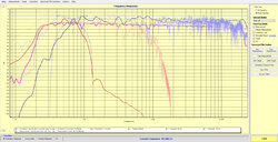
Here's what I had before, hope this helps.
 

Attachments

  • Audiolense3.jpg
    Audiolense3.jpg
    215.1 KB · Views: 62

juicehifi

Audiolense
Staff member
Joined
Feb 5, 2018
Messages
701
^based on the frequency response of the two drivers I figured they would be pretty well phase aligned in that region. Dip + dip is in phase most of the time, but now and then 180* out of phase with each other. Dip + peak is partly out of phase. Non-dip plus non-dip is in phase.

Since Audiolense phasealigns at the crossover point, it will always be in pase there after correction, but then the drivers will be somewhoat out of phase everywhere else. TTD per driver can fix that to the extent that the acoustics allows for it, but I think it is better in any case to use ar region that is benign for a crossover to begin with.
 

2234rew

Member
Joined
Nov 24, 2020
Messages
271
^based on the frequency response of the two drivers I figured they would be pretty well phase aligned in that region. Dip + dip is in phase most of the time, but now and then 180* out of phase with each other. Dip + peak is partly out of phase. Non-dip plus non-dip is in phase.

Since Audiolense phasealigns at the crossover point, it will always be in pase there after correction, but then the drivers will be somewhoat out of phase everywhere else. TTD per driver can fix that to the extent that the acoustics allows for it, but I think it is better in any case to use ar region that is benign for a crossover to begin with.

Thanks Bernt.

This is great advice to use as a starting point and then as you said in earlier reply, experiment some more.
 

jjazdk

Member
Joined
Aug 17, 2018
Messages
95
Since Audiolense phasealigns at the crossover point, it will always be in pase there after correction, but then the drivers will be somewhoat out of phase everywhere else. TTD per driver can fix that to the extent that the acoustics allows for it, but I think it is better in any case to use ar region that is benign for a crossover to begin with.

Maybe I misunderstood.. I thought the Audiolense correction filter phase-aligned the entire speaker, and not only at the crossover point(s) ?
Isn't the intention to ensure that every frequency arrives at the listeners ears at the exact same time?
 

juicehifi

Audiolense
Staff member
Joined
Feb 5, 2018
Messages
701
It phase-corrects the whole speaker ... after it has phasealigned the drivers at the crossover points. But if the drivers are out of phase between each other outside the crossover, they will work against each other after correction. And some times that will have negative consequences.
 

jjazdk

Member
Joined
Aug 17, 2018
Messages
95
It phase-corrects the whole speaker ... after it has phasealigned the drivers at the crossover points. But if the drivers are out of phase between each other outside the crossover, they will work against each other after correction. And some times that will have negative consequences.

That makes perfect sense.
 
Top Bottom