


Resurrecting a BG FS-520i PD 50 Ribbon Driver
I thought this might be interesting for you DIY/Repair it yourself types out there!
One of my long-term Hi-Fi companions gave up the ghost. The BG Radia FS520i speaker on the right side said, “NO MORE!” and the 50” ribbon driver (BG RD50) just went silent.
I had owned these speakers for over ten years buying them new and they have served me well. I played them loud… I played them softly…. They always delivered. One reason I purchased them was the LIFETIME WARRANTY. Well crap! It’s hard to exercise such a thing when the company folded five years ago. In retrospect (and reality) I guess the ten years was the lifetime of that speaker.
I had hopes of finding a replacement or getting it fixed. I took a few days to look around but could not find anything in the way of help. I did find a matched pair of the RD50 ribbon on eBay in Spain for $3600. No thanks! I looked for but found no mention of anyone capable of repairing the driver.
And, while I did replace them with a pair of GoldenEar Triton One.R’s I always thought I would try a repair on them eventually.
Well, that day has finally come! I dis-assembled that offending speaker and affected a repair.
I am excited to say I was successful in the repair attempt and that the speaker is working as it should….. At least for now! Whether my attempted repair is successful for the long-term I can’t say… But, for now, all is right in my little “Audio World”
Here's what I did..... The Repair Plan and Implementation;
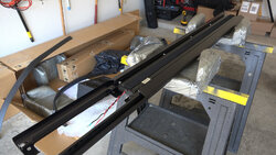
1. Dis-assemble the speaker to remove the ribbon module


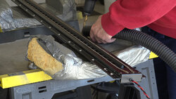
2. Once the ribbon module was completely removed from the frame I had to drill and remove all of the rivets that held the clamshell of the housing together.


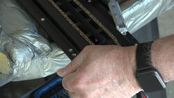
3. I had to clean the “puckey” from the contacts to get a better look at where I thought the break was. Failing that I started to pry the clamshell apart so I could get to the broken ribbon at the connecting circuit board that I had identified.


*** I left the clamshell separated and turned to find additional tools when Tragedy Struck! ***
4. The magnets that surround both halves of the clamshell decided to make a break for it and jumped the top half of the clamshell to one side. Now desperate I quickly pried the clamshell completely apart to find that the ribbon had been pushed to the side with a bit of damage to the membrane that the ribbons float on.
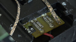
5. In addition, the circuit board at the top of the speaker was torn off and separated from all four ribbon strips! Ugh! I considered packing it in at this point but drew a deep breath and started thinking….. Hmmmmm!
6. I decided to forge ahead with a new plan. I reinforced the damaged membrane with clear packing tape and at the same time pulling the ribbon back into some semblance of the original shape.
7. After trying to bridge the breaks in the connections with solder I discovered that the ribbons were too fragile to solder to effectively.
8. New Plan Version 2.0 - I ordered some conductive foil with conductive glue to bridge the gaps but the glue would not adhere.
9. New Plan Version 3.0 - With the foil idea not working out, and after racking my poor little brain I had a sudden idea (Brain Fart). I would search for something I had played with years ago to repair broken traces on a PCB…. Conductive Silver Ink! Sure enough Amazon carries several brands! Quick as Amazon Prime during COVID-19 could deliver (four days in this case :-) I had my silver ink pen.
10. Armed with the pen I redrew the traces over the broken spots. This looked pretty fragile so I layered the silver conductive ink into at least three layers and heat cured each layer with a hair dryer. Even this I judged to be a weak connection, so I bridged each of the ink traces with the copper foil and tack soldered the foil at each end and then covered those connections with the silver ink once more. After heat curing the whole stack again, I checked continuity to find it all checked out as it should at about 4.6 ohms.
11. There were two retaining blocks (Squash Blocks) at each end of the ribbon that pushed down on the connections. These had a hard cork surface. Since I had built up the connections with the solder/conductive ink/copper foil I decided to replace the cork with some speaker gasketing material I had on had to provide a softer clinch while still restricting movement at the transitions from ribbon to connection block/PCB.
12. After checking continuity I left the whole thing alone for three days to cure. After one more good continuity check I was ready to place the top clam shell.
To make sure the top did not jump or skew to either side I used two long shaft Phillips head screwdrivers in guide holes top and bottom to guide the clamshell top into position.
With some help from my wife we pressed the top and bottom halves together and I installed one rivet at each end to secure. This was not easily done since the powerful magnets in each half of the clamshell are set to repel the two halves! But, once the rivets were in I could install some clamps on either side to make sure the halves were firmly squeezed together before installing the rest of the rivets.

14. Two smaller rivets restored the connector PCB cover.
15. I used my small signal tracer and YES!.... I heard a faint signal emanating from the speaker. So, armed with that knowledge I decided it was time to reassemble the complete speaker!
16. I started the reassembly of the speaker.

17. Once completely reassembled I carried the repaired speaker up to my listening space and connected it to the system.

IT WORKED! I was a little gun shy and did not turn it up too loud but instead left it playing at a moderate volume on the right side while my GoldenEar Triton One.R continued playing on the on the left.
While it played, I unpacked the other FS-520 and brought it back upstairs as well. I shut off the system and replaced the left Triton One.R with the newly placed FS520.
I cranked the system back up and was pleased to hear there was no discernible difference between the Right and Left FS520 either in volume or tonal characteristics.
I slowly increased the volume of the system and the speaker not only kept playing but exhibited no issues.
I left the FS520’s in the system for four days playing music and movies/videos at my normal listening levels. The speakers were performing fine when I finally swapped back to my GoldenEars!
Unfortunately, there are no other places in the house where I can really place them into service (read… where my wife will let me place them into service).
Plan 4.0 is let them set for a while and then test them again. Passing that test I will list them for sale "as is" in the Dallas area with the caveat one speaker has been repaired :-)
Color me a Happy Camper for now!
I thought this might be interesting for you DIY/Repair it yourself types out there!
One of my long-term Hi-Fi companions gave up the ghost. The BG Radia FS520i speaker on the right side said, “NO MORE!” and the 50” ribbon driver (BG RD50) just went silent.
I had owned these speakers for over ten years buying them new and they have served me well. I played them loud… I played them softly…. They always delivered. One reason I purchased them was the LIFETIME WARRANTY. Well crap! It’s hard to exercise such a thing when the company folded five years ago. In retrospect (and reality) I guess the ten years was the lifetime of that speaker.
I had hopes of finding a replacement or getting it fixed. I took a few days to look around but could not find anything in the way of help. I did find a matched pair of the RD50 ribbon on eBay in Spain for $3600. No thanks! I looked for but found no mention of anyone capable of repairing the driver.
And, while I did replace them with a pair of GoldenEar Triton One.R’s I always thought I would try a repair on them eventually.
Well, that day has finally come! I dis-assembled that offending speaker and affected a repair.
I am excited to say I was successful in the repair attempt and that the speaker is working as it should….. At least for now! Whether my attempted repair is successful for the long-term I can’t say… But, for now, all is right in my little “Audio World”
Here's what I did..... The Repair Plan and Implementation;
1. Dis-assemble the speaker to remove the ribbon module
2. Once the ribbon module was completely removed from the frame I had to drill and remove all of the rivets that held the clamshell of the housing together.
3. I had to clean the “puckey” from the contacts to get a better look at where I thought the break was. Failing that I started to pry the clamshell apart so I could get to the broken ribbon at the connecting circuit board that I had identified.
*** I left the clamshell separated and turned to find additional tools when Tragedy Struck! ***
4. The magnets that surround both halves of the clamshell decided to make a break for it and jumped the top half of the clamshell to one side. Now desperate I quickly pried the clamshell completely apart to find that the ribbon had been pushed to the side with a bit of damage to the membrane that the ribbons float on.
5. In addition, the circuit board at the top of the speaker was torn off and separated from all four ribbon strips! Ugh! I considered packing it in at this point but drew a deep breath and started thinking….. Hmmmmm!
6. I decided to forge ahead with a new plan. I reinforced the damaged membrane with clear packing tape and at the same time pulling the ribbon back into some semblance of the original shape.
7. After trying to bridge the breaks in the connections with solder I discovered that the ribbons were too fragile to solder to effectively.
8. New Plan Version 2.0 - I ordered some conductive foil with conductive glue to bridge the gaps but the glue would not adhere.
9. New Plan Version 3.0 - With the foil idea not working out, and after racking my poor little brain I had a sudden idea (Brain Fart). I would search for something I had played with years ago to repair broken traces on a PCB…. Conductive Silver Ink! Sure enough Amazon carries several brands! Quick as Amazon Prime during COVID-19 could deliver (four days in this case :-) I had my silver ink pen.
10. Armed with the pen I redrew the traces over the broken spots. This looked pretty fragile so I layered the silver conductive ink into at least three layers and heat cured each layer with a hair dryer. Even this I judged to be a weak connection, so I bridged each of the ink traces with the copper foil and tack soldered the foil at each end and then covered those connections with the silver ink once more. After heat curing the whole stack again, I checked continuity to find it all checked out as it should at about 4.6 ohms.
11. There were two retaining blocks (Squash Blocks) at each end of the ribbon that pushed down on the connections. These had a hard cork surface. Since I had built up the connections with the solder/conductive ink/copper foil I decided to replace the cork with some speaker gasketing material I had on had to provide a softer clinch while still restricting movement at the transitions from ribbon to connection block/PCB.
12. After checking continuity I left the whole thing alone for three days to cure. After one more good continuity check I was ready to place the top clam shell.
To make sure the top did not jump or skew to either side I used two long shaft Phillips head screwdrivers in guide holes top and bottom to guide the clamshell top into position.
With some help from my wife we pressed the top and bottom halves together and I installed one rivet at each end to secure. This was not easily done since the powerful magnets in each half of the clamshell are set to repel the two halves! But, once the rivets were in I could install some clamps on either side to make sure the halves were firmly squeezed together before installing the rest of the rivets.
14. Two smaller rivets restored the connector PCB cover.
15. I used my small signal tracer and YES!.... I heard a faint signal emanating from the speaker. So, armed with that knowledge I decided it was time to reassemble the complete speaker!
16. I started the reassembly of the speaker.
17. Once completely reassembled I carried the repaired speaker up to my listening space and connected it to the system.
IT WORKED! I was a little gun shy and did not turn it up too loud but instead left it playing at a moderate volume on the right side while my GoldenEar Triton One.R continued playing on the on the left.
While it played, I unpacked the other FS-520 and brought it back upstairs as well. I shut off the system and replaced the left Triton One.R with the newly placed FS520.
I cranked the system back up and was pleased to hear there was no discernible difference between the Right and Left FS520 either in volume or tonal characteristics.
I slowly increased the volume of the system and the speaker not only kept playing but exhibited no issues.
I left the FS520’s in the system for four days playing music and movies/videos at my normal listening levels. The speakers were performing fine when I finally swapped back to my GoldenEars!
Unfortunately, there are no other places in the house where I can really place them into service (read… where my wife will let me place them into service).
Plan 4.0 is let them set for a while and then test them again. Passing that test I will list them for sale "as is" in the Dallas area with the caveat one speaker has been repaired :-)
Color me a Happy Camper for now!
Attachments
-
 004 dis-assembly bass module removed 2.jpg262.8 KB · Views: 41
 -
 005 disassembly drilling out the rivets.jpg271.5 KB · Views: 42
 -
 006 disassembly removing riit heads 1.jpg205.9 KB · Views: 44
 -
 008 cleaning up the connections a bit.jpg196.4 KB · Views: 43
 -
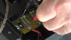 008 the broken connection 1.jpg182.7 KB · Views: 49