I use a Motu dac. There was a shelf eq in a channel that wasn’t supposed to have one. My routing table and EQ table are a bit out of control (too big) !
The reason I had a shelf EQ in another channel is that my DAC is used as my phono preamp as well. I mix the right and left channels below 150 Hz and keep them stereo above 150 Hz (thus the shelf filter). This creates a vertical rumble filter. Then, in AL, using the target, I implement a sharp 20 Hz filter for very low frequencies (which avoids the phase shift problem that eRIAA has), a notch filter at 60 Hz for any 60 Hz bleed-through from the powerline, and a RIAA correction. So in essence, I 've recreated a digital version of a phono preamp and KUB rumble filter (
https://www.analogueseduction.net/phono-stages-phono-boards/KABRF1.html).
The funny part is that I seldom listen to my LPs ! But when I do (and the disc is a new disc), it sounds great. Just liked the challenge of having everything setup perfectly.
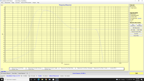
The flat measurement was needed to measure the THD+N of my virtual phono preamp. Unfortunately I realized that to do this properly, I could not use my DAC as the source for a 1kHz signal. I would have to located a 1 kHz generator that has lower distortion than the device under test. In the meantime, I figured I'd measure the real life THD+N by using a test LP. The measured noise floor was so high that I realized instrument grade measurements were irrelevant.
The flat measurement file will also serve to measure the 'filter insertion loss'. I realized that talking about loss is not very meaningful when the user has a target that's down-sloping and de facto creating a forced loss. So a speaker/room correction should be compared to a correction applied to this ideal speaker measurement with the same target. From what I can see though there is only a loss of ~1dB between the tallest correction peak and the 0dB line. The correction peaks are dependent on your speaker/room and target curve. I was under the impression that a mismatch in volume between sub and speaker (or woofer and tweeter) would increase the loss, but it does not (the louder speaker just gets attenuated to a greater degree). It still makes sense to have roughly the same volume so your microphone measurement stays in the green zone for both speakers.
I realize this is all kind of esoteric, and useless to most people...